I have this week been looking at a power amplifier that I made for a friend about 35 years ago !
It was rated at 30 watts rms per channel into 8 ohms
I made this for Steve when I was about 22 years old using what was at the time the latest thinking re power amplifiers
Input is via a low pass filter 2.2k and 220 pf to avoid T.I.D. distortion This was then fed into a npn diff pair Bc 182 these being fed via a constant current source this being a ring of 2 Bc182 output from the diif pair being fed into a Bc212 vas that had an unbypassed 100 ohm emitter resistor collector load for the vas was another Bc182.
Bias for the output pair was via a vbe multiplier yet another Bc182
The output pairs were inverted darlingtons using base stopper resistors as experiments had shown that using this system I could acheive a very stable set of outputs
I did not use a capacitor between collector and base on the vas but between the collector of the vas and base of diff pair
After extended testing i.e.35 years I have measured both dc offset worse channel being 15 mv and bias being 12 mA not bad for a design thats pre Self and blameless
This was all done using a progressive method of listening and simple instruments an Eagle signal generator and a low cost Heathkit scope I also measured distortion under 0.1% @ 1 khz at any power below clipping.
I have made a drawing re the schematic and taken photos would any one like to see them?
How does it sound ? fine mighty fine !
Regards Trev
Last edited:
This sounds oddly familiar. My guitar amplifier is of a similar age. I find it amazing how stuff just keeps going. They don't build them like that any more.
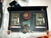
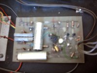
here are some pictures
I hope that these pictures attache ok
The amplifier now appears a little rough but its had a long working life !
I can even remember marking and cutting the boards by hand
This was way before the days of PC and cad software
I have also noticed that their is no dc blocking capacitor on the input to the diff pair but as the pre-amp was capcitor coupled it did not matter ( what a risk taker)
I shall post the schematic tommorow with a few more comments
This is only 1 of many hundreds of amplifiers I have made and designed over the last 40 years or so
But as they say we can all learn something new!
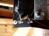
Ps the only failure in all this time has been the left hand led power indicator ( I knew these new fangled Leds were crap)
regards Trev
I hope that these pictures attache ok
The amplifier now appears a little rough but its had a long working life !
I can even remember marking and cutting the boards by hand
This was way before the days of PC and cad software
I have also noticed that their is no dc blocking capacitor on the input to the diff pair but as the pre-amp was capcitor coupled it did not matter ( what a risk taker)
I shall post the schematic tommorow with a few more comments
This is only 1 of many hundreds of amplifiers I have made and designed over the last 40 years or so
But as they say we can all learn something new!
Ps the only failure in all this time has been the left hand led power indicator ( I knew these new fangled Leds were crap)
regards Trev
Attachments
Last edited:
Very nice...real DIY work...lovely... a pity the camera cannot make close up picture
without loose it's focus... we could see these lovely construction in more details with the macro feature.
Some cameras does not have macro function, to make focus when the lenses are 10 to 20 centimeters from the target to be captured in photography.
Thank you Latala..... was good to see..from time to time real diyers appear.... a rarity those days.
regards,
Carlos
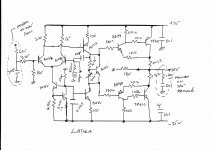
Please find hand drawn schematic of the power amplifier
I have used this scheme many times with great success However my designs that I use today have evolved from this design
To me the main advantage of this circuit is the thermal stability due to the use of the inverted darlingtons in the output stage.
I made many tests at the time that this circuit was created relating to thermal stability and can say that this was in the order of 10 times better re bias drift related to output transistor temperature when compared with both Quasi and true Darlington output stages. You will note from the earlier pictures that the bias monitor transistor is not even connected to the heatsink
I would say that this is a good design for any one looking for this power level
In this day when we have a very large selection of high performance devices it must be remembered that the devices we could obtain where very limited
especialy re operating voltage etc
regards trev
Attachments
Last edited:
I forgot to mention that The amplifier is effected by the capacitor that is connected between the Vas collector and the input to the diff pair it is 100 pf here however when I was testing this I found that distortion could be made as low as 0.02% if this was reduced to 22pf,however stability was affected I decided by listening tests that the value of 100 pf gave me the best sound and a reasonable measured performance!
To me one of the most desirable properties on any power amplifier is stability
I should imagine that this amplifier would be very good with modern devices
Like Carlos I listen to my hifi! I can measure it but in the end I decide with my ears
Regards Trevor
To me one of the most desirable properties on any power amplifier is stability
I should imagine that this amplifier would be very good with modern devices
Like Carlos I listen to my hifi! I can measure it but in the end I decide with my ears
Regards Trevor
I forgot to mention that The amplifier is effected by the capacitor that is connected between the Vas collector and the input to the diff pair it is 100 pf here however when I was testing this I found that distortion could be made as low as 0.02% if this was reduced to 22pf,however stability was affected I decided by listening tests that the value of 100 pf gave me the best sound and a reasonable measured performance!
To me one of the most desirable properties on any power amplifier is stability
I should imagine that this amplifier would be very good with modern devices
Like Carlos I listen to my hifi! I can measure it but in the end I decide with my ears
Regards Trevor
Wow, after 35 years playing, that amp is still kicking some butt, I bet you if you change those electrolytic caps for better ones, that amp will live for 35+ years more. I guess it was well made.
I think today some companies can still build very good and reliable amps. Bryston is one of them.😀
A basic design, done well can perform magnificently. There is no need to go uber fancy. This design is about as basic as you can get. The Sziklai pairs on the back end also sound very good, if you can keep 'em stable. That, and the QC topology, definitely sound better to me.
Yep...ears allow us to decide better... i could find several 0.02% (THD) amplifiers
sounding better than some amplifiers based in operational amplifiers having much lower distortions.
From time to time ...one or two low distortion amplifiers results good..others sound lifeless.
Measurements, seems to me, indicates, show us, point to us, that probably, with a big chance, the amplifier will sound good if it measure good...but this is not a guarantee... i had several surprises about that.
An accident of the destiny, that one i have made (copied, adapted or designed, or planed, or developed) has sounded so good with so small distortion measured.
regards,
Carlos
Last edited:
Hi Trev,
Nice design!
Well, just for kicks I plugged the circuit into Spice.
With 100p compensation the loop gain phase margin is 88 deg, the dominant pole is around 260Hz. With only 20p compensation the phase margin only decreases to 84.5 deg, so I think it still is stable enough. The dominant pole in this case is around 1.2KHz.
The calculated distortion with 100p at 20KHz and 51W is 0,54%, with 20p, 53.1W 0.16% (no surprise here).
Just curios, what made you choose the compensation that you used instead of using it as a "regular" Miller capacitance at the VAS?
Regards, Peter
The schematic looks alot like the design of the Plastic Tiger power amplifier from the fabled Southwest Technical Products Company of Texas. Dating from around 1968.
I've never understood why sziklai pairs were qualified as "unstable", and this is one of the reasons why the tiger had a bad reputation.
You should probably replace those supply electrolytics soon, or they might cause lack of bass response, I think...
nice amplifier!
I've never understood why sziklai pairs were qualified as "unstable", and this is one of the reasons why the tiger had a bad reputation.
You should probably replace those supply electrolytics soon, or they might cause lack of bass response, I think...
nice amplifier!
At the time It was stated by I think Linsley Hood that this was a better method that would render the amplifier less prone to slew rate limiting
To be honest I started using this method of compensation and never gave it another thought I have used it hundreds of times
I still have my Sugden test set that I used to measure distortion and noise etc
This would be done typically @ 100 hz 1khz and 10 khz
I totaly agree that the caps should be changed now and may do so in the future
My designs have moved on in all kinds of ways this was the thinking of 35 years ago
I have no experience of Spice modeling
Is there a sample program that I can download?
The Tiger I became aware of only about 5 years ago via the web
I do not claim any origional thinking in this design and only mentioned it as I love invered darlingtons re thermal stability and found them no worse than any other output stage re oscillation provided they were fitted with stopper resistors as shown
I have also also done many mosfet units but always come back to inverted darlingtons
The exception is the new Sanken Darlingtons fitted with on chip temperature compensation I have had superb results with these !in my latest design cloned from the Albarry amplifier
I did also do a much improved version of this 35 year old design that had seperate power supplies for the voltage stage and a larger power supply dedicated to the output stage only
To me it was a revelation transient attack and vice like grip in the bass
would any one like to see the drawing re that
These are not concepts but practical amplifier
Regards For now Trev
ah, OK. Who's Linsley Hood, a reverred audio designer?At the time It was stated by I think Linsley Hood that this was a better method that would render the amplifier less prone to slew rate limiting
To be honest I started using this method of compensation and never gave it another thought I have used it hundreds of times
I still have my Sugden test set that I used to measure distortion and noise etc
This would be done typically @ 100 hz 1khz and 10 khz
I totaly agree that the caps should be changed now and may do so in the future
My designs have moved on in all kinds of ways this was the thinking of 35 years ago
I have no experience of Spice modeling
Is there a sample program that I can download?
Nor do I, and I guess you can download it from their website, whatever it might be. I only simulate things in reality on my protoboard.
What do you mean by "re thermal stability" and "re that" ?The Tiger I became aware of only about 5 years ago via the web
I do not claim any origional thinking in this design and only mentioned it as I love invered darlingtons re thermal stability and found them no worse than any other output stage re oscillation provided they were fitted with stopper resistors as shown
I have also also done many mosfet units but always come back to inverted darlingtons
The exception is the new Sanken Darlingtons fitted with on chip temperature compensation I have had superb results with these !in my latest design cloned from the Albarry amplifier
I did also do a much improved version of this 35 year old design that had seperate power supplies for the voltage stage and a larger power supply dedicated to the output stage only
To me it was a revelation transient attack and vice like grip in the bass
would any one like to see the drawing re that
These are not concepts but practical amplifier
Regards For now Trev
Linsley Hood was until last year 1 of the greatest all time British audio designers an origional thinker and father of the 10 watt class A amplifier amongst many others! If you Google him his work will keep you reading for days. What I mean by thermal stability is for the bias ie no signal standing current to remain at the set value no matter what the output transistor temperature! With Qausie or normal Darlington their is a considerable drift hence the thermal compensation devices that you often see.
The problem with feedback thermal compensation is that the devices have to warm up before it works and their is always thermal lag/delay
Regards for now Trevor
The problem with feedback thermal compensation is that the devices have to warm up before it works and their is always thermal lag/delay
Regards for now Trevor
Hi Trevor,
I have been using LtSpice, probably the most popular spice programs. It is a full featured program, free, can be downloaded from Linear Technologies web site : Linear Technology - LTspice IV Downloads and Updates , you not even need to register. The reason it is free that it is full with the macromodels of all the LT chips, LT considers it as a marketing tool.
Here is a web page to a LtSpice tutorial: LTspice Tutorial
There is also an excellent Yahoo discussion group on LtSpice.
You have to take the results of a simulation always with a grain of salt, and it is no substitute for engineering knowledge. On the other side it gives a tremendous insight into the circuit operation. It is always a ton of fun!
Try it, it will be another useful tool!
Good luck, Peter
- Status
- Not open for further replies.
- Home
- Amplifiers
- Solid State
- 35 years old and still going strong