Hi,
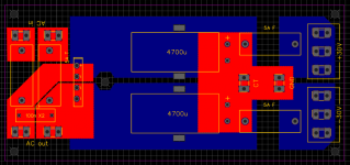
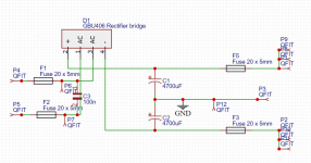
I'm designing a power supply for an amplifier project using +-30V rails. It's a straightforward design but I wanted to check that I hadn't missed anything. I've included fuses on the secondary and DC rails and a small capacitor across the secondary. The GND terminal on the PCB will go to a separate star ground point. Douglas Self says that local decoupling capacitors on the amplifier boards should be grounded to the main filter capacitors and not the star ground so perhaps I should add an additional connection next to the CT connection.
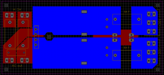
I have completed all connections on the PCB with copper fill as I'd like to use a 1oz board due to the big price difference. My only concern with this is that the pins on the bridge rectifier still only make contact with the copper over a small area. I have included square cutouts in the board to secure the electrolytics with cable ties, mounted flat on the board.
At the moment, there is no provision for a heatsink for the rectifier. I do not know if this will be necessary. I have seen guitar amplifiers (which this is for) using the same type with no heatsinking so I don't know what the real world circumstances require.
All criticism is greatly appreciated!
Thanks,
James
I'm designing a power supply for an amplifier project using +-30V rails. It's a straightforward design but I wanted to check that I hadn't missed anything. I've included fuses on the secondary and DC rails and a small capacitor across the secondary. The GND terminal on the PCB will go to a separate star ground point. Douglas Self says that local decoupling capacitors on the amplifier boards should be grounded to the main filter capacitors and not the star ground so perhaps I should add an additional connection next to the CT connection.
I have completed all connections on the PCB with copper fill as I'd like to use a 1oz board due to the big price difference. My only concern with this is that the pins on the bridge rectifier still only make contact with the copper over a small area. I have included square cutouts in the board to secure the electrolytics with cable ties, mounted flat on the board.
At the moment, there is no provision for a heatsink for the rectifier. I do not know if this will be necessary. I have seen guitar amplifiers (which this is for) using the same type with no heatsinking so I don't know what the real world circumstances require.
All criticism is greatly appreciated!
Thanks,
James
Attachments

As an additional question, is there likely to be a problem with using thermal reliefs on the solder pads, in terms of reduced current capability?
Thanks,
James
Thanks,
James
I think one pair of fuses on input would be fine.
Thermal relief is a balancing act.
Not so little there is little track to carry current.
Not so much that the heat is sunk out of the soldering iron and you cant solder the joint.
Thermal relief is a balancing act.
Not so little there is little track to carry current.
Not so much that the heat is sunk out of the soldering iron and you cant solder the joint.
Thanks,
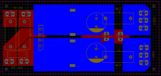
Hopefully I've got the amount of thermal relief right. I've redesigned the board slightly so that the bridge rectifier can mount flat against the board with a heatsink fixed on top. I thought it was best to play it safe. Do you think I'll be okay with 1oz copper? The price difference is massive.
Thanks,
James