I wish you all Happy New Year!!
I got MQ FS-030 and I’m trying to use it for building a 300B SE amp. I understand this output transformer is restricted to 60mA. All the schematic that I found was operating with 430V on Plate and 80mA with 880R or 1k of Cathode resistor.
If I’m trying to use for the current schematic, what is operating condition for 60mA? What is the plate voltage and the cathode resistor for 60mA operation?
Would you recommend the best 300B SE schematic for FS-030, please?
Would you advise me, please?
Thanks in advance.
K.
Attachments
Here's the typical output characteristics of a JJ 300B.
The horizontal line means the plate current you'd like to use. The red line means 60mA.
And you can find the corresponding plate voltage and grid bias.
For example we select Ua=300V then the intersection point means we need Ug=-60V to meet the 60mA target Ia at Ua=300V.
With desired Ia=60mA and Ug=-60V, the correct resistance value for the self bias resistor should be R=|Ug/Ia|=1Kohms.
The main HV should have at least Utot=|Ug|+Ua=360V. Usually the primary section of the OPT will cause a voltage drop of about 10Volts, so the main HV should be 370Volts then.
http://www.trioda.com/tools/triode.html
You can try to simulate the output stage on this website. It can't set the load line impedance and DC operating point separately, so it's a little hard to adjust. But I have to say that different 300Bs will have different characteristics. The results can't be guaranteed.

The gap for 60mA is not the whole story on those transformers. I suggest you do searches of the Magnequest forum on the AudioAsylum. With an "Exact Match" of FS-030 , you can put names like , mqracing, Paul Joppa, Braubeat, (one name for each search). Most will maybe not be of much interest but there are a few bits there that should help.
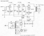
Attached is a schematic of a circuit taken from that forum. (for a different output tube I built the Komuro front end used in it using the two sections of a 6DN7 and it worked great.)
Also attached is the archived page from the Magnequest website in 2004 giving figures for those transformers being used well above 60mA. (SO don't limit yourself before doing some more research.)
In answer to one of his customers , MIke LaFevre (the maker of the FS-030) posted a link to This Site
And also if you hurry you might still have time to get a board from Tubelab_com (on diyAudio) for his TSE-II. He's closing his shop at the end of this year so only a couple of days to go. Lots of support for your build on diyAudio if you go that route.
Good luck
Attachments
Thank you so much for your help.The gap for 60mA is not the whole story on those transformers. I suggest you do searches of the Magnequest forum on the AudioAsylum. With an "Exact Match" of FS-030 , you can put names like , mqracing, Paul Joppa, Braubeat, (one name for each search). Most will maybe not be of much interest but there are a few bits there that should help.
Attached is a schematic of a circuit taken from that forum. (for a different output tube I built the Komuro front end used in it using the two sections of a 6DN7 and it worked great.)
Also attached is the archived page from the Magnequest website in 2004 giving figures for those transformers being used well above 60mA. (SO don't limit yourself before doing some more research.)
In answer to one of his customers , MIke LaFevre (the maker of the FS-030) posted a link to This Site
And also if you hurry you might still have time to get a board from Tubelab_com (on diyAudio) for his TSE-II. He's closing his shop at the end of this year so only a couple of days to go. Lots of support for your build on diyAudio if you go that route.
Good luck
I never thought about audio asylum forum.
I just started to search it as you advised me
It will take me down to the deep search.
I really appreciate your help and advise.
Thank you so much.
Thank you so much for your help.View attachment 1252957
Here's the typical output characteristics of a JJ 300B.
The horizontal line means the plate current you'd like to use. The red line means 60mA.
And you can find the corresponding plate voltage and grid bias.
For example we select Ua=300V then the intersection point means we need Ug=-60V to meet the 60mA target Ia at Ua=300V.
With desired Ia=60mA and Ug=-60V, the correct resistance value for the self bias resistor should be R=|Ug/Ia|=1Kohms.
The main HV should have at least Utot=|Ug|+Ua=360V. Usually the primary section of the OPT will cause a voltage drop of about 10Volts, so the main HV should be 370Volts then.
http://www.trioda.com/tools/triode.html
You can try to simulate the output stage on this website. It can't set the load line impedance and DC operating point separately, so it's a little hard to adjust. But I have to say that different 300Bs will have different characteristics. The results can't be guaranteed.
It’s a great help to me.
I should have to print the WE300B characteristics and draw the line of it and try to find the load line.
Thank you.
Kwongb
Before you settle on a schematic, please take a look at the Western Electric 300B datasheet:
http://www.tubebooks.org/tubedata/we300a_b.pdf
Looks at page 4, the chart of various quiescent operating conditions.
Start by picking 3000 Ohm plate load, and current of up to 60mA.
50ma is OK too, the transformer will produce slightly more power at a slightly lower frequency, than with 60mA.
Pick a plate voltage, plate current, 3000 Ohm load, and see the results of:
Output power
2nd harmonic distortion
3rd harmonic distortion
There are several good operating values for your MQ transformer; you decide what are the best tradeoffs for you.
Then find a schematic that can use those quiescent operating conditions from page 4 chart.
Happy deciding, designing, building, and listening!
Thank you so much for your data sheet info.
This gave me info for operating points selection.
Thank you very much
This gave me info for operating points selection.
Thank you very much
The time ran out for an edit so am posting it here.
According to the Magnequest sheet and Asylum posts the FS-030 can be run at 90 or even 100mA, so it appears you're not limited at all.
It's a bit counter intuitive when the rated current is said to be 60mA. If me, before committing to a proper finished build , if you have the parts on hand to do it, I'd breadboard a simple circuit (like the one on Kent GIlbert's site) to try the FS-030 at those higher currents and confirm it doesn't saturate or run warmer than you like, though from what I read on that forum, it looks like it will not be any problem.
While Magnequest is now closed, the forum is still working and friends of the brand still look there from time to time. You could always try posting there, or on the tube diy forums to see if there's anybody around who is using them. I think quite a few were made.
Gordon Rankin did a design for the WE91 circuit using them. Maybe talk to him as well.
Also noted Paul Joppa's comment that its peak inductance at low power was at a point suited to 2a3.
G'luck !
I believe the FS-030 was Mike's first SE design (1992), and he was notoriously conservative in his ratings - especially in the early days. I wouldn't hesitate to operate it at up to 80mA.
In the earliest 300B data sheets, the tube was specified at 300v/60mA int a 3K load. The later 1950 specifications were at 300v/62mA/3Kohms and 350v/60mA/4Kohms. I think this was the real origin of Mike's 60mA spec. Here are 3 suitable operating points:
300v/60mA/3K
350v/70mA/3K
400v/80mA/3K
In the earliest 300B data sheets, the tube was specified at 300v/60mA int a 3K load. The later 1950 specifications were at 300v/62mA/3Kohms and 350v/60mA/4Kohms. I think this was the real origin of Mike's 60mA spec. Here are 3 suitable operating points:
300v/60mA/3K
350v/70mA/3K
400v/80mA/3K
Hearinspace,
Thank you so much
Your warm hearted advices are a big help to me.
As you wrote, I’ve been searching the Gordon Rankin WE91 design for FS-030 after I read the comments on the forum but I couldn’t find it yet.
I think I just tried it for higher operating conditions as you advised.
I really appreciate your advice.
Thank you.
Paul Joppa,
Thank you very much.
I’ve been reading your comments on the Audio Asylum forum.
Now I clearly understand it from your advice.
I really appreciate it. Your comments solve all my questions at once.
Thank you
Thank you very much.
I’ve been reading your comments on the Audio Asylum forum.
Now I clearly understand it from your advice.
I really appreciate it. Your comments solve all my questions at once.
Thank you
Hearinspace, . . .
And Paul Joppa,
Can you point me to the link that Hearinspace wrote:
Also noted Paul Joppa's comment that its peak inductance at low power was at a point suited to 2a3.
What is the difference in performance the FS-030 at low power, for:
a 2A3: 60mA, -45V bias, 250V plate to filament, rp = 800 Ohms
Versus
a 300B: 60mA, -61V bias, 300V plate to filament, rp = 700 Ohms
In theory, I expect the difference in performance of the FS-030 at low power . . .
Would be dominated by a 'typical' 8 Ohm loudspeaker, that had a minimum impedance of 6 Ohms, and a maximum impedance of 25 Ohms.
With similar DHTs at equal low power, and plate impedances, rp of 700 Ohm versus rp of 800 Ohms, would that result in much difference in sound for
an FS-030?
Yes, or No?
I am just trying to understand the 2A3 being optimum for low power, versus another tube.
Thanks!
Hearinspace,
Thanks! . . . Now I understand.
Looking at the data - - - the FS-030 is "rated" at 60mADC. (It can muster 5% more inductance at 60mADC/3.3watts - a good 2A3 point).
I ran the Electra Print Audio 5k 60mA rated single ended transformers at about 34mA from some used 45 tubes.
20 Hz looked real pretty!
Perhaps there are more 2A3 fans, than there are 300B fans on Tubes / Valves. Y / N?
45 tubes, anybody?
I have enjoyed designing, building, and listening to all 3 of those tube types.
Have Fun!
Last edited:
"Perhaps there are more 2A3 fans, than there are 300B fans on Tubes / Valves. Y / N?"
I don't know, but early in the Audio Asylum neck of the woods the two were the mainstream DHT's along with the 45 and after that relatives like the 6a3 and 6B4G. I think Bottlehead and their peep's contributions to the DIY scene are underestimated, and twenty years ago their two top kits were 2a3 and 300B.
I don't know, but early in the Audio Asylum neck of the woods the two were the mainstream DHT's along with the 45 and after that relatives like the 6a3 and 6B4G. I think Bottlehead and their peep's contributions to the DIY scene are underestimated, and twenty years ago their two top kits were 2a3 and 300B.
I wish you all Happy New Year!!
I got MQ FS-030 and I’m trying to use it for building a 300B SE amp. I understand this output transformer is restricted to 60mA. All the schematic that I found was operating with 430V on Plate and 80mA with 880R or 1k of Cathode resistor.
If I’m trying to use for the current schematic, what is operating condition for 60mA? What is the plate voltage and the cathode resistor for 60mA operation?
Would you recommend the best 300B SE schematic for FS-030, please?
Would you advise me, please?
Thanks in advance.
K.
The second schematic is the classic Joe Roberts version of the WE 91A from Sound Practices magazine. That's the first amp I ever built, with FS-030 output transformers. It's a great amp. That was almost 30 years ago, and my wife still talks about those monoblocks and why I didn't stop there. ;-) Wish I still had those FS-030's but I moved away from SE amps and "loaned" them to a friend. They're still doing service somewhere back East. ;-)
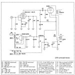
Today seems to be the day for this so here's a post with Paul Joppa's derivative of the M91, which is part of this long thread .
Last edited:
Hearinspace, . . .
And Paul Joppa,
Can you point me to the link that Hearinspace wrote:
Also noted Paul Joppa's comment that its peak inductance at low power was at a point suited to 2a3.
What is the difference in performance the FS-030 at low power, for:
a 2A3: 60mA, -45V bias, 250V plate to filament, rp = 800 Ohms
Versus
a 300B: 60mA, -61V bias, 300V plate to filament, rp = 700 Ohms
In theory, I expect the difference in performance of the FS-030 at low power . . .
Would be dominated by a 'typical' 8 Ohm loudspeaker, that had a minimum impedance of 6 Ohms, and a maximum impedance of 25 Ohms.
With similar DHTs at equal low power, and plate impedances, rp of 700 Ohm versus rp of 800 Ohms, would that result in much difference in sound for
an FS-030?
Yes, or No?
I am just trying to understand the 2A3 being optimum for low power, versus another tube.
Thanks!
I must have done something wrong; my comments are missing from post #18.
Hearinspace posted a link (in post #13) to my old comments. I no longer remember what I was thinking at the time (10+ years ago!), but in general operating points are pretty malleable; I agree with 6A3sUMMER that the variable impedance of real-world speaker impedances should dominate minor variations in transformer impedance, plate voltage, current, and plate resistance.
Nonetheless, we built an amp (now out of production) designed for use with modern high-dissipation "2A3s". Operating point was 300v at 60mA into a 3000 ohm transformer. A switch was included to reduce the current to 50mA so that older 2A3s could stay within their 15W plate dissipation limit. It seems like a small change, but it is in fact easily audible. I was quite surprised!
----------------------------------------
I'll take this opportunity re-iterate my operating point calculation, since it's been a long time since I last posted it. It is theoretical, based on the three-halves power law which is well approximated by highly linear triodes such as 300B, 2A3, 45, 845, 211, etc. :
For a chosen quiescent plate-cathode voltage and plate current, choose a load load line that intersects the zero-bias plate curve at twice the chosen quiescent current. The relationship is:
RL = RB - 2.38*rp
RL is the load impedance
RB is the beam resistance, quiescent plate-cathode voltage divided by current
rp is the plate resistance at the chosen operating point
This leaves a small current margin at the high voltage/low current end of the load line, amounting to about 3% 2nd harmonic distortion for highly linear triodes. If the tube has a lot of local feedback, the cutoff margin approaches zero, A less linear tube will leave a larger current margin, make less power, and exhibit more distortion. Being theoretical, it's merely a good starting point rather than an exact calculation.
- Home
- Amplifiers
- Tubes / Valves
- 300B Schematics for MQ FS-030