Hello,
Planning to build 300B based low gain line stage based of Bartola Valves design. Limited experience before (only kit building), so trying to keep it safe first time - Will be using Bartola Gyrator and HT Supply PCB, and Coleman fillament regulators. Could somebody recommend a suitable high quality mains transformer and rectifier tube combination to get 250 B+ and 2x6,3V secondaries for the heaters? Help much Appreciated.
Planning to build 300B based low gain line stage based of Bartola Valves design. Limited experience before (only kit building), so trying to keep it safe first time - Will be using Bartola Gyrator and HT Supply PCB, and Coleman fillament regulators. Could somebody recommend a suitable high quality mains transformer and rectifier tube combination to get 250 B+ and 2x6,3V secondaries for the heaters? Help much Appreciated.
Attachments
Are you sure, that 300B the most suitable for this?
Most of them (mainly new commercial products) microphonic as hell if you use it in linestage.
If you want to build DHT preamp, try to use any HT transformer -for example- 230-0-230V/100..250mA and 5V/2.5..3A (for tube rectifier), even if it toroid.
sample:
https://www.tme.eu/en/katalog/trans...:1445082;449:1491933,1491936,1523423,1491947;
For R.C. regulator I always use separated low voltage transformer with dual bobbin (low parasitic capacitance between primary and secondary).
BTW for 5V DC (with R.C. regulator) need to use 5V+ 4..5V R.C headroom (depends of version of regulator) raw DC voltage.
6.3V AC is insufficient for this, I used 9V AC.
sample:
https://www.tme.eu/en/katalog/trans...:1445764;444:1445638;445:1445082;449:1445101;
Last edited:

Hi Euro21,
I currently use 300B in a line stage (Bottlehead BeePre2) and I very much like the signature. Want to build something similar and learn about component/architecture influence on end sound quality.
So should I not be afraid of resulting higher HT, with lets say 230-0-230 AC and just tame it with a resistor before sending it to B+?
Thanks for the tip on the R.C. regulator 9V requirement.
Active load (CCS or Ale's gyrator) almost insensitive to value of B+.
The only criterium that it will be greater than:
anode voltage + anode swing peek + 20..40V headroom.
In line stage the swing is marginal, so Ua+40V -or greater- is enough.
If B+ greater than calculated, only the dissipation of active load will growing, so (if the anode current not too high) even 300V DC isn't too high in this case.
So usable PT secondary will be OK -for example- for 200V to 260..270V AC.
Thanks!
So I could use lets say 2x Hammond 266L14 (7V@4A) for the filament DC as per Coleman datasheet recommendation and a Lundahl LL1649 1x230 1A, 2x 6.6V 3.1A for HT power supply. If I choose to have a tube rectifier with 5V filament, just use a dropping resistor to get those 6.6V to 5V?
Or alternatively, use something like LL1683
and adapt one of the Bartola Valves schematics?
Your advice takes me far, thank you!

So I could use lets say 2x Hammond 266L14 (7V@4A) for the filament DC as per Coleman datasheet recommendation and a Lundahl LL1649 1x230 1A, 2x 6.6V 3.1A for HT power supply. If I choose to have a tube rectifier with 5V filament, just use a dropping resistor to get those 6.6V to 5V?
Or alternatively, use something like LL1683
| 250-0-250V / 0.16A | 6.6V / 3A | 5.2V / 3A | 48V / 0.1A |
and adapt one of the Bartola Valves schematics?
Your advice takes me far, thank you!
After a little bit of research on-line, making the choice is getting more and more complicated. For filament supply I will go with the 2x Hammond 266L14
For HT My current options are listed below. Any advices, or maybe I am looking in the wrong direction?
Lundahl:
LL1649 200,06 €
1x 230 V @ 1.0A
4x6.6 @ 3.1A
Indel:
https://www.tme.eu/en/details/tsl100_001/transformers-with-fastening/indel/tsl-100-001/ @79.42
2x 260V @ 0.12A
2x 3.15 @ 3A
2x 5 @ 2A
https://www.tme.eu/en/details/tsl100_002/transformers-with-fastening/indel/tsl-100-002/ 72,85€
230V @ 0.3A
7.2V @ 4.5 A
Edcor
https://www.don-audio.com/Edcor-XPWR012-240-Class-X-Power-transformer 138,41 €
350V (175-0-175) at 100mA center tapped
6.3V (3.15-0-3.15) at 2A center tapped
5V at 2A
https://www.don-audio.com/Edcor-XPWR146-Power-transformer 153,68 €
200V at 250mA
6.3V at 4.5A.
LL 1649 is a bit (more than a bit, 250VA) extreme choice for 2x30mA load.
LL1683 is better alternative.
2x250V/80mA and 5.2V/3A good for any tube rectifier.
Hammond 266L14 (7V/4A) is perfect for -new, version 9- 5V R.C. regulator.
If you use any active load for DHT, more simple HT supply is enough (CCS or gyrator has at least 60dB CMRR).
Using cLCRC is enough.
p.s. Indel TSL 100-001 is enough. I used it too.
sample
Last edited:
The unbypassed cathode resistor value of 1k could present noise problems, in any DHT preamp.
The Raw DC of the filament supply is floating, so the leakage current from the power transformer will flow though the cathode resistor. This is a common-mode current, so filtering or regulation does not reduce it. The current is 50Hz in Europe, and for a 230V supply the leakage is a common mode current of ca. 6-10µA, depending on the leakage capacitance the Bela mentioned in post #2. 6µA through 1k makes 6mV, which is much too high for a preamp. Bypassing the 1kΩ resistor removes the noise. You can use DC Link capacitors to reach ca. 120µF (example: 3x 40µF) if you want to avoid electrolytics.
If you already have a 300B preamp, the best solution is:
using the same gain and bypassing that you have in the Bottlehead design. You can experiment later, with other biasing or even bypassing, to check the effects (and sound).
Just to be clear, you are recommending to A) Start with original design (330R +220uF 50V) and test if it works altogether. Use existing/similar voltage regulator for DC. B) After testing that everything works ~O.K. modify Pre-Amp grain/bypassing according to Bartola valves schematics, however bypass the 1k with 120µF, right?Bypassing the 1kΩ resistor removes the noise.
The 1k resistor also sets the anode current of the 300B. You can try it with a lower value, if the anode load can support higher current.
The type of anode load also affects the gain (step down transformer obviously reduces it). If the gain of your present Bottlehead preamp is less than 4, it's worth checking that the power amplifier's input can support the peak signal voltage, for 300B + gyrator with a bypassed cathode resistor (gain of ca. 4). If it's ok, bypass Rk with 100 to 160uF.
The type of anode load also affects the gain (step down transformer obviously reduces it). If the gain of your present Bottlehead preamp is less than 4, it's worth checking that the power amplifier's input can support the peak signal voltage, for 300B + gyrator with a bypassed cathode resistor (gain of ca. 4). If it's ok, bypass Rk with 100 to 160uF.
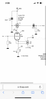
A toroidal transformer of 2x180v and 2x6.3V with suitable amperages got into my hands. I know it can by noisy, yet for experimentations sake, I will also use a large 2000kVA isolation transformer (well... I just happen to have one). I guess I can start building now until the right transformers arrive. I want to use similar design like my previous line stage: LT1764 regulator for DC filaments, 3k plate resistor (for now, later upgrade to CCS), 220R grid stop resistor, 100k grid leak resistor, 330R bias resistor bypassed with 220uF, center tapped. Schematics attached. Some questions if somebody can step in:
I want to build an external block for power supply, should I locate the LT1764 close to the 300B, or it can be integrated into power supply?
Any modification for schematics that I should do?
I want to build an external block for power supply, should I locate the LT1764 close to the 300B, or it can be integrated into power supply?
Any modification for schematics that I should do?
Attachments
should I locate the LT1764 close to the 300B
Yes, that is best. Make sure it has an input capacitor right close to the chip . Check data sheet for type & value of the capacitor.
Is that schematic for the preamp you are using now?
If so, please measure the voltage across the 330R (Rk). The new circuit should aim to run the same anode current. It will be likely to have lower distortion than with Rk = 1k.
Thanks for reply.
Datasheet suggest a min value of 10uF types Z5U, Y5V, X5R or X7R. Currently I have 22uF, I will add in one 22uF for input and 22uF for output in the DC regulator and mount it next to tube socket.
Yes, just the physical layout will be different with a remote power supply.Is that schematic for the preamp you are using now?
Currently there is no input capacitor (just two pairs or 20,000 uF 10V in the raw DC stage with a dual 4.5mH choke in between).Check data sheet for type & value of the capacitor.
Datasheet suggest a min value of 10uF types Z5U, Y5V, X5R or X7R. Currently I have 22uF, I will add in one 22uF for input and 22uF for output in the DC regulator and mount it next to tube socket.
10.1V, so.. 30.6mAIf so, please measure the voltage across the 330R (Rk). The new circuit should aim to run the same anode current.
Hello Bela,Using cLCRC is enough.
I am trying to do enough reading to understand what on earth am I doing, yet...8th grade physics is still a tough cookie. I have traced my current power supply schematics. I would not like to go very far from it, just take some small steps and keep it safe:
1) Have 260V RMS as input power supply (Indel TSL 100-00)
2) Keep the schematics the same, with no major changes. Using PSU2 I have tried to simulate this, and I get only 1.6mV ripple at the output with 80mA load. Is there any sonic benefit changing 1 section from RC to LC? and getting the ripple into the uV range, when using an active B+ load (Gyrator)? Using the same scheme I should get ~304 on the B+ before gyrator, which should still be O.K.
Thanks for the kind help.
As I wrote in #4, if you use active load, the B+ -correct- value isn't important, only the active device dissipation changing.
The PSRR of these devices enough large, so simpler PSU (higher ripple on B+) is even allowed.
So -IMHO- C-R-C-R-C smoothing don't need, simpler C-R-C or C-L-C is enough for smoothing.
The use of symmetric resistors (R2,R3 and R4, R5) is unnecessary, only in "upper" need. It is important for "ground" position of PSU too.
If you want to "larger dissipation" in PSU (and not in active device), use larger resistor/s/ between capacitors, even in added R-C chain (its mostly unnecessary for smoothing, only has a voltage reduction function).
The safety discharger resistor is important that need to works near the last capacitor!
If the resistance (resistor, choke DCR) enough low between smoothing capacitors, after the turn off the discharging resistor discharge all capacitors (before the last, then another).
The most important thing, that the last capacitor would be the "more best" in PSU.
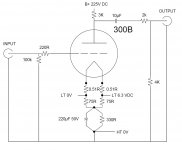
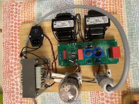
Updated schematics with component selection. I hope to start assembling end of next week once the LT transformers arrive.
My current 300B line stage is operating at a lover voltage operating point at 120V Anode voltage and using a 330R/220uF cathode bypass ~10V, 30mA. I will start with that and then will move on to schematics operating point of 190V, 30V 1k/120uF Bias, 30mA
My current 300B line stage is operating at a lover voltage operating point at 120V Anode voltage and using a 330R/220uF cathode bypass ~10V, 30mA. I will start with that and then will move on to schematics operating point of 190V, 30V 1k/120uF Bias, 30mA
Attachments
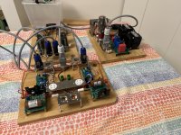
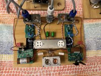
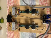
Breadboarded the setup over the weekend. Voltage checks are good, need to change the heatsinks on the Coleman regulators, tighten the bolts, give it a good shake and hopefully will have time to insert tubes and run some tunes though it. The put in some electrolytics 100uF for for cathode bypass and have some 120uF DC-links ready if that works well.
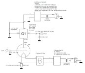
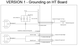
First time doing a setup not in a chassis, perhaps somebody could comment of the signal ground -> earth connection. Currently there are two "stars" - one on the main board (Input/output/Cathode bias/HT-) and one on the HT power supply (Safety earth/Transformer 2x/HT-). Signal path is grounded though HT- on the HT power supply board. I am using antiparallel diodes, R22 5W + 10uF. Perhaps I should leave the HT supply board "floating" and connect ground only to the star of the signal board, passing the IEC ground though one of the umbilical's? Schematics attached.
@Rod Coleman, I know your regulators should be floating, yet I have shielded the LT umbilical cord. Hope that's not an issue. My complements on the design and the manuals.
Attachments

Last edited:
- Home
- Amplifiers
- Tubes / Valves
- 300B line stage Mains transformer