Hi all,
please, bear with me, I come from the loudspeaker forum.
I did some simulation to perfect a 3-way passive speaker, and the impedance curve is bogging me. I know there is a difference for valve and SS. Now, considering that I build them for both, being able to change the xover accordingly, for 1- old or new valve amps, 2- hi-fi Denon PMA-735R ampli, 3- a PA ampli from QSV - GX5/GX3.
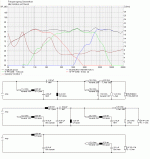
So having this curves on fig1, what RLC-Series Resonant Circuit, for impedance linearisation, should I use, if necessary.
a) Circuit for tweeter: 11R/0,65mH/2,0uF
b) Circuit for top Mid: 20R/2,20mH/5,1uF
c) Circuit for low Mid: 12R/9,00mH/47uF
d) Circuit for woofer (driver's) resonance in the corresponding cabinet: 12R/35,00mH/210uF
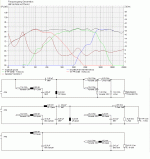
Xover from fig1 with RLC a) and RLC b) on.
Attachments
- Status
- Not open for further replies.

