I have four Cerwin Vega CLS-215 3-way speaker enclosures in a home audio system powered by a Crown XLS 2502 and everything calibrated via Mini DSP/REW with very good results. The crossovers employ inexpensive parts, including cheap poly caps, several electrolytics, inexpensive iron core inductors, cement resistors, etc. I would like to upgrade the crossovers and speaker wiring.
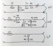
CV was unwilling to provide a schematic for the crossover, although I was able to find front/back images of the PCB and most parts values. I’ll get the rest when I remove one (a bit of a pain). My plan is to upgrade key components in the crossovers while sticking as closely as possible to the original parts values. I was able to draw this schematic, which you can see attached here.
From the research I’ve done, I gather that capacitor upgrades would be C1, C2, C3/C4, C5, and C6 in order of importance. Space permitting, I will try to get rid of the electrolytics, or perhaps just construct new crossover boards from scratch if it makes sense.
I realize there is a debate as to the effectiveness of a small bypass cap in the tweeter circuit (and midrange?). If I were to use one, would that be on C1 or C2?
I’d like to go with air inductors (tweeter and midrange) if I can match the resistance of the originals. If not, I’m considering just upgrading all to better laminate types.
Unless the values are out of whack, I’m not sure if it’s worth upgrading the resistors.
There is a PTC resettable fuse on the tweeter positive output. I have no plans to remove it unless it adversely affects the sound quality(?).
What changes would you make? Opinions welcomed and greatly appreciated!
Attachments

Welcome to the forum! I'll kick off the discussion.
Regarding the PTC, it should not adversely affect the sound quality.
It will add a fraction of an ohm to the tweeter attenuation in normal operation.
Regarding the PTC, it should not adversely affect the sound quality.
It will add a fraction of an ohm to the tweeter attenuation in normal operation.
Thank you for clarifying that. I didn't think it presented an issue, but wanted to ask. Incidentally, in the series (XLS) that followed this one, CV added a second PTC between L1 and (-) and eliminated C2 and R1, thus going from a 3rd order to a 2nd order arrangement.
Some more thoughts from me until the experts chime in. 🤓
You say you are getting "very good results", so may simply be suffering from a particularly itchy form of that common ailment - crossover upgradeitis!
Changing crossover components can change the voicing of a loudspeaker which may or may not sound better to your ears.
The manufacturers have the appropriate types of capacitor in the appropriate places and your electrolytics will still be within tolerance.
Not everyone agrees that bypass capacitors make an audible difference, but I suppose you would put one on both C1 and C2.
You will find that air core inductors that match the resistance of the larger value iron core inductors will be very large and very expensive.
I agree that it is not worth upgrading the resistors!
EDIT: Regarding the midrange filter, I think I am right in saying that the 4 uF film cap may be regarded as a bypass for the 30 uF electrolytic.
Last edited:
Yes, crossover "upgradeitis" is correct! These are all valid points. I understand and expect changes, hopefully with results that further enhance clarity and resolution. I would anticipate that upgrading certain components, particularly capacitors in the HF and Mid sections would present audible improvements over the cheap seats, but I am aware there are no guarantees. As far as inductors, I would be more hesitant about changing them than capacitors, and yes, at least the LF inductor (and possibly Mid) would likely not be practical to switch to air core. In that case, I could go with upgraded parts (e.g. Sledgehammer laminates) or just leave them as-is. I feel it's mostly a matter a question of where to put attention (and money) before we get too far down the road of diminishing returns.
L2 e L4? values?I have four Cerwin Vega CLS-215 3-way speaker enclosures in a home audio system powered by a Crown XLS 2502 and everything calibrated via Mini DSP/REW with very good results. The crossovers employ inexpensive parts, including cheap poly caps, several electrolytics, inexpensive iron core inductors, cement resistors, etc. I would like to upgrade the crossovers and speaker wiring.
CV was unwilling to provide a schematic for the crossover, although I was able to find front/back images of the PCB and most parts values. I’ll get the rest when I remove one (a bit of a pain). My plan is to upgrade key components in the crossovers while sticking as closely as possible to the original parts values. I was able to draw this schematic, which you can see attached here.
From the research I’ve done, I gather that capacitor upgrades would be C1, C2, C3/C4, C5, and C6 in order of importance. Space permitting, I will try to get rid of the electrolytics, or perhaps just construct new crossover boards from scratch if it makes sense.
I realize there is a debate as to the effectiveness of a small bypass cap in the tweeter circuit (and midrange?). If I were to use one, would that be on C1 or C2?
I’d like to go with air inductors (tweeter and midrange) if I can match the resistance of the originals. If not, I’m considering just upgrading all to better laminate types.
Unless the values are out of whack, I’m not sure if it’s worth upgrading the resistors.
There is a PTC resettable fuse on the tweeter positive output. I have no plans to remove it unless it adversely affects the sound quality(?).
What changes would you make? Opinions welcomed and greatly appreciated!
Thanks
Hi Ted,
I’ve done some crossover upgrades before and if I were you I would probably change only the capacitors. I don’t know about the benefits of using bypass caps, but I guess it doesn’t hurt to try and if you decide to do so, then it makes sense to put one on both C1 and C2.
As for the C3 (4uF) and C4 (30uF) I think whoever built the crossover needed this very specific value of 34uF and since it’s not a standard one, they used two in parallel in order to achieve it.
- Home
- Loudspeakers
- Multi-Way
- 3-Way Crossover Upgrade Help Sought