Hey guys can you point me in the right direction to make a 3.3V regulated PSU suitable to drive the above DAC..
You might take a look at what I did for the pcm2707: http://www.ecp.cc/NOS-USB-DAC.html
It essentially uses a cap, a resistor and a choke before the transformer, then another cap and resistor after the transformer all for cleaning the AC. Then it uses a rectifier with 100pF snubber caps, a 1800uF cap + a .1uF film cap to smooth, a LM7805 to preregulate, then a 680uF cap, then a high quality LDO 3.3V regulator and then 0.1uF ceramic bypasses next to any pin powered. There should probably be a small film cap before the second regulator, but I ran out of space.
It essentially uses a cap, a resistor and a choke before the transformer, then another cap and resistor after the transformer all for cleaning the AC. Then it uses a rectifier with 100pF snubber caps, a 1800uF cap + a .1uF film cap to smooth, a LM7805 to preregulate, then a 680uF cap, then a high quality LDO 3.3V regulator and then 0.1uF ceramic bypasses next to any pin powered. There should probably be a small film cap before the second regulator, but I ran out of space.
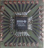
3.3V PSU to drive PCM2706 USB DAC
Build a simple 3-4 transistor 3.3V regulator.
Use 3x1.5V batteries to give regulator input at 4.5V.
How much current does a PCM2706 take?
...........................
Datasheet says supply at 3.3V:
min 3.0 Volt, max 3.6 Volt
and typical supply current 23 mA
This is a lot of current, for using battery supply.
They will be empty in a short time.
I have some 1700mAh NIMH 1.5 penlights....
Can you point me towards a diagram for that transistor regulator please?
Can you point me towards a diagram for that transistor regulator please?
Why not use 4 to 5 of this 1.5V NIMH in series, followed by a 1000uF cap, regulated with LM317 as described in the datasheet (variable voltage). Add a 470uF cap after the regulator and preload the circuit with a bleeder resistor with at least 5mA eg. 680 Ohm.
Works great. The PCM2706 is sounding best with 3.9 to 4VDC. Works for months in my setup.
As soon as the DAC is working (try it first with windows and be happy when the system begins to configure a human interface device and an audio device), I recommend you to download (all for free, just google) the following software:
- ASIO4ALL: the better sound system than the basic windows software.
- Exact Audio Copy: to make perfect rip off from CD
- LAME: to integrate in EAC as converter
- foobar: the player software.
Happy ears!
Franz
Franz G said:Why not use 4 to 5 of this 1.5V NIMH in series, followed by a 1000uF cap, regulated with LM317 as described in the datasheet (variable voltage). Add a 470uF cap after the regulator and preload the circuit with a bleeder resistor with at least 5mA eg. 680 Ohm.
Works great. The PCM2706 is sounding best with 3.9 to 4VDC. Works for months in my setup.
LM317 needs a voltage across input-output of something like 2.5-3 Volt to work.
If you set output at 4.0 Volts, batteries must hold like 6.5-7 Volt.
This means 6-7 NiMH cells.
Why a discrete transistor based regulator is better.
You can make a custom lowdrop regulator.
The difference between input and output voltage is very low.
I have designed such a regulator using 3 small signal transistors.
My design goal was low dropout voltage and very low supply current consumption.
This to save battery.
At no load my transistor regulator works at only 0.150 mA ( 150uA ) supply current.
And at 50 mA output, output is kept at 5.00 Volt as long as input voltage is more than 5.20 Volt.
Dropout = 0.20V at 50 mA.
Thanks Franz, had some good news, sounds like I can have my tranny on monday allready and it was only R20, which is like the equavalent of $2.50, I also found a 12Mhz crystal so apprat from PSU I'm all set...
One slight problem is, I couldnt get a 3.3V reg that can work on 8V, so I took a 8V a 5V and a 3.3V, hope it works if I step down with them.
One slight problem is, I couldnt get a 3.3V reg that can work on 8V, so I took a 8V a 5V and a 3.3V, hope it works if I step down with them.
I don't know why you can't use a 3.3v reg with a 8V input. At 23mA, you only need to dissipate about 1/10th of a watt of heat.Nordic said:One slight problem is, I couldnt get a 3.3V reg that can work on 8V, so I took a 8V a 5V and a 3.3V, hope it works if I step down with them.
At any rate, the LM317 is not as low noise as some other regulators, so it may not be the best option here. On the other hand, if you use a small inductor and decouple the pcm's pins well, you can get rid of the high frequency noise.
Hey D, you must just keep on hanging around here, I'm realy out of my depth when it comes to digital circuits..., going to the shop quickly to get some Coke then I'll come enter what components I got for the PSU, If I have to guess, no LM regulators.. probably 78XX stuff.
Nordic
I recommend you the following procedure:
First, use two or three NiMH in series, load them with 1k resistor and measure the voltage.
Anything between 3 to 3.9V is O.K.
Now you can try your USB DAC. When it works correctly, you can proceed to step two: make a fine PSU.
Franz
I recommend you the following procedure:
First, use two or three NiMH in series, load them with 1k resistor and measure the voltage.
Anything between 3 to 3.9V is O.K.
Now you can try your USB DAC. When it works correctly, you can proceed to step two: make a fine PSU.
Franz
My hands stink now, just completed sawing off the excess PCB... Franz man, I still don't know how to thank you.
Franz man, I still don't know how to thank you.
Man, you promised me, not to talk about that in the forum!
For the others: I've sent some of my sample chips and smd soldering trials to Nordic (because I like his avatar) 😉
The PCM2706 is already soldered in a adapter board, but he got a piece of four adapters, three of them unusable.
So, he had to cut it out.
Regards
Franz
Attachments
Lol I'm sure they don't know what I thanked you for, but yeah, guys, Franz is my current hero... Boy do I have something to send to you, sadly its totaly legal.
BTW, you got mail
BTW, you got mail
---------------------------------------------------------------------------------Nordic said:Hey guys can you point me in the right direction to make a 3.3V regulated PSU suitable to drive the above DAC..
If you want really low noise, go for the ALW regulator in this forum. Once you have built one, the rest are easy. NO packaged regulator can match it's performance.
My DAC sound much better powered by this even though it has multi stage regulation after a switching regulator.
🙂
I'm no expert, but this much I have managed to find out: regulators don't do much to filter out high frequency noise, and that is a big part of the battle in a DAC. It is not that failure to filter it out will lead to a bad project, but that properly doing so will make it that much better. Also, while batteries help things, they are not necessarilly a panacea. They do still have some noise. Also, regulators are likely to add a little bit ofnoise, so even with a battery there will be some. A ferrite bead in series with the supply to the pin, and a decoupling cap very close to the pin can do wonders. But, as I say, you shouldn't let this hold up getting a project done, but you should consider it for the second try when you are trying to make improvements.
I'm no expert, but this much I have managed to find out: regulators don't do much to filter out high frequency noise, and that is a big part of the battle in a DAC. It is not that failure to filter it out will lead to a bad project, but that properly doing so will make it that much better. Also, while batteries help things, they are not necessarilly a panacea. They do still have some noise. Also, regulators are likely to add a little bit ofnoise, so even with a battery there will be some. A ferrite bead in series with the supply to the pin, and a decoupling cap very close to the pin can do wonders. But, as I say, you shouldn't let this hold up getting a project done, but you should consider it for the second try when you are trying to make improvements.
Thanks, I'm allready bussy with version 2, as I saw some problems with my first attempt, no harm done as I haven't soldered anything...got some ferite beads on a PCB from a PC screen somewhere, think I will pirate a few, why is there no seperate digital and analog power supplies... or is it not worth it...?
This morning I will start her up, think I soldered the last connection last night... also got a 3.3V supply working after a few tries... eventualy I used a LM317 a 240R resitor and a 1k pot.(and caps etc, but thats not important now). I have a 7.2V 1.2VA tranny connected to the regulator.
I also calculated that the second resistor should be somewhere over 600ohms... but strangely enough when I measure the two connected legs on the pot they read something like 260ohms...
As long as it doesn't break anything... anyone have any advice, measurements I can make with multimeter etc...?
I also calculated that the second resistor should be somewhere over 600ohms... but strangely enough when I measure the two connected legs on the pot they read something like 260ohms...
As long as it doesn't break anything... anyone have any advice, measurements I can make with multimeter etc...?
- Status
- Not open for further replies.
- Home
- Source & Line
- Digital Source
- 3.3V PSU to drive PCM2706 USB DAC