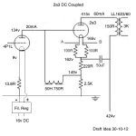
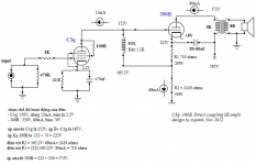
I saw a circuit by D.Perez in 2005 which was described as a kind of Free Lunch or Monkey. I don't know the right term for it - looks closer to a Monkey. I'm interested in trying it out so worked out this schematic as a first draft. I have all the parts. This would require a preamp - I have a 4P1L preamp already. I have a PSU around 425v hence that choice of HT. Could raise the HT if there was a compelling need. I thought to run the 2a3 at the usual 250v, 60mA.
Could anyone familiar with this kind of circuit comment on it? All ideas welcome.
Andy
Could anyone familiar with this kind of circuit comment on it? All ideas welcome.
Andy
Attachments
Last edited:
I'm looking at this type of circuit now. As I understand it your 20mA to the input plate won't go through the cathode resistor and therefore there is only 40mA through the cathode resistor which will put you at 100V instead of 149v which will then throw off all the other values. Someone correct me if that thinking is whack thanks....
EDIT, in other words replace the 2k5 with a 3k7
EDIT, in other words replace the 2k5 with a 3k7
Ah - I see what you mean. I calculated 60mA through the combined cathode resistors under the 2a3, but as you say one of them has another 20ma through it. Back to the drawing board.
Andy, what I meant was the 20mA through the input is pulled through the 2A3 to create the total 60mA (less strain on the power supply). Therefore only 40mA is going through the Rk (2k5). I hope that makes sense AND is correct thinking. Summing currents at the junction of the 2k5/50Hchoke/220R we get 60=40+20 so that is my thinking there per kirchoffs? law.
Damn - that means I'll have to use an OPT gapped for 80mA. I do have a LL1620/80mA in a 300b SET so I'd have to steal that one. Back to the drawing board again!
If I want to keep the 149v at the junction of the two resistors, then the bottom one which has 80mA through it looks like about 1.8K. Is this right now?
No the opposite, the resistor sees 40mA and sources the remaining 20mA bias from the input tube current. The 2A3 still sees 60mA.
Here is a good link I was actually reading last night:
Jeremy Epstein's Free Lunch
"The trick of recycling some of the 2A3's current to power the driver cuts the demand on the power supply somewhat Â* you are basically getting a free power supply for the driver. Also the power that was dissipated as heat in the 2A3's cathode resistor is no longer wasted, but becomes the driver's quiescent power dissipation, allowing the amp to run a bit cooler."
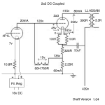
Hello again - I deleted the message you replied to because it was rubbish, as you say. Is this on the right lines now? I can see that 120v on the plate of the 4P1L is a bit low so the whole thing should go up about another 20v. That means I'll have to think about modifying the PSU. Anyway, I just want to make sure my calculations are correct first. I'm trying to get the "book" operating point of 250v, -45v and 60mA.
Attachments
That all looks about right though I admit I am not sure yet on how to get the 2x100Rs figured in on the cathode voltage. However, it looks okay but you say you want the 250v/60mA/45v book bias but have 80mA through the plate now. I think your first version with a 3k7 instead of 2k5 was exactly what you wanted...but again, I am a newbie to hifi (only been looking at this stuff for like a week!). I'm sure there's a good chance I am screwing you up and causing confusion. I wish someone else would chime in here. Seems we are both thinking about this the same way now though, just the 80mA through the plate is a problem. Well, not a problem, just not what you wanted.
Looks good to me. Not sure how the 10.8R is being figured on the input cathode - do you mind explaining that?
Member
Joined 2009
Paid Member
Looks good to me. Not sure how the 10.8R is being figured on the input cathode - do you mind explaining that?
This is filament bias. The DC filament supply goes through the filament and also the cathode resistor. The filaments of the 4P1L in triode are calculated at 1.9v and 650mA. So the current through the cathode resistor is 650mA for the filament plus 20mA for the tube. The point of filament bias is to achieve a very small cathode resistor that does not need to be bypassed. It needs a very clean DC supply, like a Rod Coleman regulator. More on all this in the long "26 pre amp" thread.
Andy
Andy,
You came up with the exact same numbers I did. Here's how I derive them:
First determine the operating points for the two tubes based on the B+. You have done that and it looks good: 250V and 60 mA for the 2A3, that puts the grid at about -45V; we now know that the grid will be at 165V minus 45V or 120V. Now we can determine the operating point of the 4P1L as we know that the plate voltage will be 120V.
From the 4P1L data we can determine that for 120V on the plate and 20mA current, the bias will be about -6.75V and the mu about 11. You will have an input sensitivity of about 4V (45V/11) so may need a preamp.
We can now fill in some of the rest of the values. If the choke has a DCR of 750r we know that .02 * 750 = 15V so the ‘bottom’ cathode resistor will drop 120V + 15V or 135V. So the cathode resistor needs to be 135V / .04A = 3375 ohms (the total current is 60mA so we deduct the 20mA the 4P1L draws from the total current). Now we need to determine the bias resistor for the 2A3. 165V – 135V = 30V; so 30V / .06A = 500r. We have 50r already so we can start with a 450r resistor as the ‘top’ cathode resistor.
In the end though, the tubes never quite agree with the operating points and the voltages never quite agree with the ones “on paper”. I usually use a variable resistor for each of the two cathode resistors and dial it in to conform to the tubes in the real world. Further, I would buy a dozen or so 4P1L tubes and select the ones that best conform to the requirements of the amp.
Good luck with the build.
So the current through the cathode resistor is 650mA for the filament plus 20mA for the tube.
Got it now. I was wondering how ohms law applied to a 10.8R resistor with 20mA...I should have once again looked at the datasheet for the tube to see it is a DHT filament!
EDIT, and they are cheap, and plentiful (it seems)...hmm
Got it now. I was wondering how ohms law applied to a 10.8R resistor with 20mA...I should have once again looked at the datasheet for the tube to see it is a DHT filament!
EDIT, and they are cheap, and plentiful (it seems)...hmm
Last edited:
I saw a circuit by D.Perez in 2005 which was described as a kind of Free Lunch or Monkey....
Could anyone familiar with this kind of circuit comment on it? All ideas welcome.
Andy
this style circuit is my favorite. I think it is one of the best schema cause of the simplicity and sound quality. It is also my plan in near future.
one my friend did this circuit with 417WE driver for 300B. He give many compliments for it.
above is old version with small OPT.
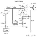
here is new plan with more power 🙂
here is new plan with more power 🙂
Attachments
Last edited:
Hey Andy,
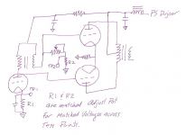
I see you use the other solution whereas Epstein takes the driver voltage directly from below the 2*100ohm via a resistor in series with the anodechoke. Do you see any advantage with the one you did choose?
This reminds me of an idea for a PP-version on the same theme by Dave Slagle. Go to page 2 for the monkey-versions.
The thread is here:
:: View topic - Summarizing smartest conventional amp designs.
Attachments
Last edited:
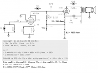
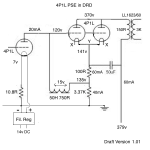
How about this for a PSE version with 4P1Ls in triode? Voltages are a lot lower. Operating point would be 229v a-k, 60mA and -21v. This is what I have in my PSE 4P1L amp right now, with the outputs in filament bias, driven by a 4P1L in filament bias through a Hammond 126c interstage. 4P1L filaments would be 1.9v, all in parallel, and 2x650mA = 1.3A.
Attachments
- Home
- Amplifiers
- Tubes / Valves
- 2a3 DC coupled