Hi! This is my very first post here. I'm so grateful for all the tips and ideas I've found here over the years, so I hope this post might give a little bit back.
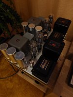
I just finished a monoblock build of 2A3-40:s in push pull fixed bias, with a parallel coupled 5687 as input and driver, via a Tamura A-351 interstage and splitter. The power supply is choke input with a 8H 250 mA choke, but preceded by a small 0.5 uF 1500V PIO cap. Smoothing caps are one 100uF for the output, and two more for the input, all motor run caps.
I run the output tubes at 305V and about 65mA.
The sound is so powerful it's almost scary! It must be because of the choke input power supply, which I truly recommend. All iron is vintage from Japan, which means I use a step down transformer to power them here in Swden, but it works great!
Attachments

Very nice looking amps.
I have a similar pair I built using 6c45p driver and Lindahl interstage transformers. I like them a lot.
Care to share a schematic?
I have a similar pair I built using 6c45p driver and Lindahl interstage transformers. I like them a lot.
Care to share a schematic?
The 2A3-40 ia good tube.Hi! This is my very first post here. I'm so grateful for all the tips and ideas I've found here over the years, so I hope this post might give a little bit back.
I just finished a monoblock build of 2A3-40:s in push pull fixed bias, with a parallel coupled 5687 as input and driver, via a Tamura A-351 interstage and splitter. The power supply is choke input with a 8H 250 mA choke, but preceded by a small 0.5 uF 1500V PIO cap. Smoothing caps are one 100uF for the output, and two more for the input, all motor run caps.
I run the output tubes at 305V and about 65mA.
The sound is so powerful it's almost scary! It must be because of the choke input power supply, which I truly recommend. All iron is vintage from Japan, which means I use a step down transformer to power them here in Swden, but it works great!
I don't like the chocke input but is a personal approach.
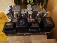
In photo two amps I built time ago, double p-p of 2A3-40
Hello,
I only recognise the Tamura iron. I have dozens of Japanese magazines but i never saw the other two brands.
Of course you did not hear the amp with capacitor input BUT it is true a choke input with a nice quality choke will make your amp much easier. It is like a V8 engine.
I never used a small cap in front of the choke input usually it is used to get a little more dc voltage output. However if you make it to big it will start working as a choke input. Did you put a load resistor across the cap to draw a minimum current. It seems you have solid state rectifier so the high voltage will go up pretty high when the tubes are not glowing yet.
Greetings,Eduard
I meant if the cap in front of the choke input is to big it will start to work as a capacitor input
All High Voltage B+ need to have a bleeder resistor.
Why?
Safety First!
Prevent the "Surviving Spouse Syndrome"
You can put the bleeder Before the choke, But . . .
I prefer putting it After the choke . . . because it will slightly reduce the higher voltage of the un-loaded B+ that occurs when the output tubes are cold.
Putting it before the choke does not reduce the un-loaded B+ voltage.
I Do like to use Choke Input B+ filters whenever I can (some secondary voltages are too low to get the B+ voltage that I want).
If you design from scratch, and purchase the power transformer appropriately, you can always use a Choke Input B+ Filter.
The hardest thing about Choke Input filters is finding a Quality Choke that works well, and that is Quiet.
The next hardest thing is to be sure the Choke magnetic field does not affect the rest of the magnetic parts, specifically the output transformers, and especially the Interstage transformers; and you need to use Aluminum chassis, even if you have to use thick Aluminum for strength.
Angular Orientation, and enough spacing between the power transformers and chokes "transmitters" Versus the interstage and output transformers "receivers" are the requirements for low hum.
Magnetic Steel chassis are horrible; transmit the power transformers and chokes to the interstage and output transformers.
I once had a Partly magnetic steel chassis. Only the folds in the metal were magnetic (corners, and edge folds).
My one magnetic steel chassis causes a headache every time I use it as a test bed for a new design of mine. Hum.
My aluminum chassis amplifiers have less than 100uV hum (< 0.1mV). Without global negative feedback, by the way.
Still not low enough for sensitive headphones (use a load and attenuator to take care of the hum when using headphones).
Just my 2 Cents ($0.02)
Last edited:
Hi Mr Ed,Very nice looking amps.
I have a similar pair I built using 6c45p driver and Lindahl interstage transformers. I like them a lot.
Care to share a schematic?
Can you share your 6c45p driver and Lundahl interstage PP amp schematic ?
Regards.
Yes, choke input sounds very good. In the early days of the DHT revival, in the 1990's, magazines like Sound Practices made a big deal about choke input supplies. Unfortunately it's not practical for some builders, but it does make for a good sound. I would be interested to see your schematic as well.
The choke is a Zebra and the power trans is a Sansui P30B, probably 50's stuff? I borrowed the idea of a small decoupling cap before the choke from Lynn Olson's Amity amp, but I'm actually not sure why he's using one. If it's mainly for switch off surge protection or for optimising the hum waveform, I don't know. I happened to have a nice Jensen pio pair that fit the bill perfectly, waiting to be used since 20 years or something.. I have bleeders in there at 4x18k, similar again to the Amity, and the rectifier is a GZ34 - so soft start B+.Hello,
I only recognise the Tamura iron. I have dozens of Japanese magazines but i never saw the other two brands.
Of course you did not hear the amp with capacitor input BUT it is true a choke input with a nice quality choke will make your amp much easier. It is like a V8 engine.
I never used a small cap in front of the choke input usually it is used to get a little more dc voltage output. However if you make it to big it will start working as a choke input. Did you put a load resistor across the cap to draw a minimum current. It seems you have solid state rectifier so the high voltage will go up pretty high when the tubes are not glowing yet.
Greetings,Eduard
My wiring is not pretty at all, and I have about 5mV of hum on the output, but my speakers are at 92dB, so I can't hear it unless I put my ear right up to the drivers 😃
Check them for insulationhappened to have a nice Jensen pio pair
I got in the past some trouble mainly with copper foil
The point of the small cap in front of the first choke is to reduce the AC ripple on the choke enough to avoid stressing it, while still acting as a choke-input supply. Originally, high-voltage choke-input supplies used "swinging" chokes, which were designed with variable inductance and could handle the ripple. A modern, inexpensive choke will sometimes "dance" or vibrate if used as an input choke.
Well yes, but I find it hard to believe Olsen would use an inadequate choke, given the high quality of the other components he uses. The value of that small cap was also chosen in relation to the value of the choke, so I suspect there's some kind of tuning going on as well.
It's not about the choke being inadequate or Lynn using cheap components. A swinging choke would be very expensive nowadays and difficult to source. It's simply to reduce some of the strain on a choke that wasn't necessarily designed for a choke-input design. The very small value of the cap has little effect on the output voltage of the supply.
Hello,
If you take a Lundahl LL1638 it can take 300 volts of ripple when being used for a choke input supply. Of course it would not be smart to use a 30 $ choke as a choke input because here we also have a substantial current running.
You could simulate in psud how much extra dc voltage output you would get by using the 0,5 microfarad cap i think it could be rather big. Let me guess 40 volts.
If you build this kind of amp you should not try to save money on the input choke and i guess the original poster used a decent one.
I dont know the original rectifier but the cap after the choke has a rather big value or not if the dcr of the choke is not to big.
Greetings,Eduard
I don't think that small a cap increases the rectifified voltage much, if at all, which is the point. Look at the design. 570-0-570, with choke input the rectified voltage would be 513vdc. Add the drop across the damper diodes, the choke and output transformer, and you're probably about right at his specified 466vdc for the output tubes. If the cap increased this by 40 volts he'd be way over that. In my experience you have to get above 1uF for the input cap for the supply to begin acting like a cap input supply.
I found a previous thread about a small cap in front of choke in a choke input supply: https://www.diyaudio.com/community/...-throws-noise-like-crazy.304457/#post-5003213
It seems clear to me from those discussions that the purpose of such a cap is to spare the rectifiers from big current transients, mainly at shut off. Makes sense, or what do you think? 😄
It seems clear to me from those discussions that the purpose of such a cap is to spare the rectifiers from big current transients, mainly at shut off. Makes sense, or what do you think? 😄
0.5 uF: 60 Hz power mains; With 120Hz full wave rectification; Xc = 2650 Ohms
Just an estimation:
With an 80mA load, the peak to peak ripple is 2650 Ohms x 0.08A = 212V peak to peak; 106V on the average.
0.5uF before the choke almost certainly raise the B+ Voltage on a pseudo choke input power supply by at least 40V.
Pseudo, because of the 0.5uF.
Where are all you fans of power supply software???
Check out my statements above using your favorite PSUD or whatever it is called!
Then report back.
Surprise me!
THANKS!
Note: 0.5uF and 10H is resonant at 71Hz.
Last edited:
- Home
- Amplifiers
- Tubes / Valves
- 2A3-40 PP with choke input PSU sounds so powerful!