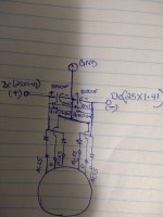
Hi folks, I want to make something newer and maybe better ac to DC supply for my 840watts stereo amplifier and I got a 1000watts quad 25-0 ac transformer with Byc10(with heatsink) diodes . I tried to art the diagram that I want to use for the AC to DC power supply, I know my art kinda funny , will you guys take a look at my diagram and please let me know is that diagram ok to use on not. Your reply will be appreciated guys. Thank you
Attachments
Your diagram should work. You can also use two bridges and get a slightly better use of the transformer.
How to use 2 bridges ?? Diagram please
Hi shovon,
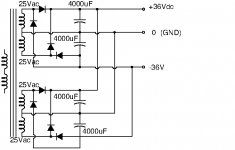
Diagram appended. Your design uses one winding in each set at a time during a cycle.
This one uses all windings twice during a cycle. The current sharing relies on the four windings having close to the same voltage and their winding impedance. The current sharing will not be ideal but not poor either.
Your 8000uF are split up in 2x4000uF in my diagram.
8000uF is very little for a 1000W power supply. Do you actually mean 80000uF?
Bleeding resistors and HF capacitors I have left out to keep the diagram simple.
Attachments
Last edited:
> 8000uF is very little for a 1000W power supply.
It is adequate for 2*8r load totem poles.
BUT I don't see 840 Watts from +/-36V with any likely impedance. Straight into 8r this is 72 Watts/channel. BTL is 288 W/ch, 576W stereo. OK, if the load impedance is near 5 Ohms it does work-out near 800 Watts. However BTL into such a low impedance does (I agree) suggest more like 10,000uFd total (four 10,000uFd in your plan), or sag-buzz will be like a $10 guitar amp (except far louder).
- Status
- Not open for further replies.