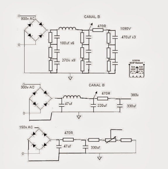
The schematics are below.
5 to 10 minutes after switch on, the high frequencies as SSSSSSSSSSSS begin to deteriorate with noise and distortion but the mid frequencies, mid bass and bass perfect very clear. but olny when listen music without music any noise or hum, only the high frequencies listen with noise.
I have changed same things in the schematic:
Cathode led now are with 2 red led in parallel with the bias at 2v, with this bias the anode now is on 145v
Now PSU 390v + CCS = 145v + 6e5p + 2 led (red) 2V
the tube 211 1065v with 62mA (measured) and fix bias -54v
At the begin I thought that need to run more hour to break and begin to open more, but after 60hour I am sure the that I have a problem because with the blue led and 3.2v bias the sound in the high frequencies never have been very good I change the coupled capacitor 0.1uf silver mica for 1.5uf PIO k75 ( both NOS Russian ) with the PIO the sound is more gentle, but I am unhappy in the high frequencies.
Possible Problems:
The cooler of the DN2540 are not enough
The resistor of the CCS 1k and 400 Ohm heat to much and begin to be imprecise.
Led in cathodes are not a good idea for CCS load or any system
DN2540 are fake or nor run correctly.
More ideas and solutions???
I begin to think in change the CCS for conventional resistor load but in this case I am not sure in the 6e5p gain 30 in triode mode can drive the -54v of the 211 bias
An externally hosted image should be here but it was not working when we last tested it.
An externally hosted image should be here but it was not working when we last tested it.
Last edited:
The schematics are below.
1.) 4k7 is not part of the cascode CCS. I you use it as the voltage dropping resistor, also use 22-47uF 450V capacitor /from the CCS B+ to the ground/.
2.) 470R as setting resistor of CCS is too large, CCS current about 3mA. Try 47..62R (30..25mA).
3.) Trioded 6E5P is happy over the 25-30mA region.
Look this datasheet: http://www.hagtech.com/blog/images/6e5p.jpg
Ug: -3V, Ia: 30mA, Ua: about 160V.
I you want about 120Vpp swing at the output of the driver (2*54V -211 grid bias- + 10% overhead), the anode voltage swing is between 100 (160V-swing/2) and 220V (160V+swing/2).
The cascode CCS stabil voltage region about 30-50V over the maximum swing, thus 220V+30..50V= 250...270V need as power voltage of the CCS.
4.) Dissipation of the upper FET of the CCS about 3W.
But in this case I think that the dn2540 are fake because the current now is 22mA per tube ( measured ), maybe this is the problem
Thanks
I check the 4 pcs DN2540 and the measured form drain-to-source give 11 to 9.7 Ohm, the same as original.
Maybe the 140v Va and 2v of the bias is not a happy region for 6e5p
Maybe the 140v Va and 2v of the bias is not a happy region for 6e5p
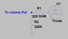
A 1K ohm grid stopper resistor right at the socket of the 6E5 would be a very good idea, it could be oscillating.
I like grid stoppers on 211 as well, again right at the socket, particularly if wiring is long.
Did you measure something around 11V across the 470 ohm resistor to arrive at a CCS current of 22mA?
You show a blue led with a VF of 3.2V in the schematic, but mention 2V in your post. Something does not add up.
How about some pictures of how it is built so we know that it is not an issue with component layout.
I run the 6E5P at 190V, 26-30mA, 3.6V bias with Cree SiC Schottky diodes in my 833C amps. The grid stopper IS needed on the 6E5P, as I found an overshoot on the scope square wave without it; 220R works well.
It's loaded in a mu-follower configuration with an AOT2N60 MOSFET on top to drive the 833C direct coupled.
It sounds fantastic to me.
It's loaded in a mu-follower configuration with an AOT2N60 MOSFET on top to drive the 833C direct coupled.
It sounds fantastic to me.
Well I return to blue led at 3.2v bias and the Rset change to 180R a now run at 28mA 12,4v on the 470R
but when the amp is hot high notes of the piano have noise agian as a breake tweeter.
Ideas?
I think that the CCS need bigger dissipator or cooler. now I use

but when the amp is hot high notes of the piano have noise agian as a breake tweeter.
Ideas?
I think that the CCS need bigger dissipator or cooler. now I use
This heat sink is too small (it's only good for 0.5-1W dissipation).
Try Aavid or Wakefield anodized heat sinks (To220) with 3-5 C/W thermal resistance.
Sample:
637-20ABP Wakefield | Mouser
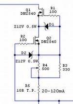
I think you toasted DN2540 FETs, or someone is dead (G-S overvoltage).
Try protection zeners.
Try Aavid or Wakefield anodized heat sinks (To220) with 3-5 C/W thermal resistance.
Sample:
637-20ABP Wakefield | Mouser
I think you toasted DN2540 FETs, or someone is dead (G-S overvoltage).
Try protection zeners.
Attachments
In this case this is the problem sure, beacuse all arround is ok.
This is my first experience with mosfet before all that I've made have been pure tube amp..
This is my first experience with mosfet before all that I've made have been pure tube amp..
I have mine clip-mounted on the chassis with a Sil-pad type insulator. No problems with overheating that way.
follow the problem
I remove the CCS and now use a 9k4 load resistor. (I like more without the CCS now is more natural or realistic sound)
But the problem follow, distorsion in high frequencies.
low and medium frequencies perfect but with the pianos in high horrible.
Medium very very clear rich and very good headroom.
saxo ok
voices ok
Drums ok
violin one ok
violin gruop bad
instruments group in high bad
piano in high frequencies very bad, distorsion as blow
With the amp in on, no noise only a litle hum of the amp
Pot 50k
Grid to ground 220k
6e5p 170v 22mA cathode 3,2v Blue Led
211 1060V 62mA bias -54v
Maybe same capacitor of the B+ are bad
Impendances.......
I dont know.
Did you install the 220 OHM grid stopper resistor Magz suggested? It is highly likely that your 6E5 driver is oscillating. This resistor should be mounted in series with the wiring to the grid pin. (Mount it right at the pin)
Sometimes inserting a 10 ohm resistor or ferrite bead in series with the plate lead right at the socket also helps.
Sometimes inserting a 10 ohm resistor or ferrite bead in series with the plate lead right at the socket also helps.
Attachments
Good suggestions so far, and I suspect that the tubes are oscillating. But you might also want to consider that the tube(s) are bad.
Kevin I was thinking the same many schematic with pentodes have 200 ohm to 1k as grid stopper I am not sure but is true that with low volume and the pot at the begin ( 50k) dont listen the noise . maybe this is the problem.
I change all tubes with the same problem.Good suggestions so far, and I suspect that the tubes are oscillating. But you might also want to consider that the tube(s) are bad.
have a lot of 6e5p ( I can sell or change 🙂) , this amp have been finish 5 days ago, with some 6e5p the problem is bigger, but this is my first DIY amp that I make all, the desing is mine I can not check any schematic to know if all is ok., I apreciate a lot all your suggestions
I have seem that the pot have e a lilte mistake.
Must be 1 in 2 out 3 ground and I have 1 out 2 in 3 ground gulty ?
Last edited:
- Status
- Not open for further replies.
- Home
- Amplifiers
- Tubes / Valves
- 211 tube amp problem Help