Don't try this at home, kids. Or do, but make sure you get really high wattage resistors. 😀
In another thread someone asked why you can't just design a crossover using 2 caps. One in series and one in parallel. This follows the same idea. Well, you can if you add resistors. I'm not responsible for any fires caused. 😉
Of course, this is purely an academic exercise, with apparently no practical value, but who knows.

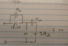
Same idea as above but with caps. In this case the tweeter and woofers have been reversed from post #1.

I’ve used capacitor-free crossovers in several of my builds. If the tweeter is efficient enough, you can get rid of R2, and just have two inductors and one resistor.
Lookup the “Acoustic Reality” crossover for the series variant.
Subjectively I find RL high-pass filters a touch more transparent and revealing, compared to a capacitor, but that could just be my imagination. I’m curious if anyone has done a more rigorous comparison or taken measurements of the difference.
As you say, you do need beefy resistors. Also watch out that the overall impedance doesn’t drop too low.
Hi, I got these on an active system 🙂 Resistor on tweeter is to reduce amplifier noise, while the parallel inductor helps retain electrical damping on driver main resonance. Woofer doesn't really need a resistor, and you could use cheap thin wire inductor to add some resistance if you wanted. The woofer series inductor reduces distortion generated in the driver motor, like current drive, but maintaining electrical damping on it's resonance. Passives to manipulate circuit impedance, DSP to shape frequency response, so it's two way with only few parts and few amps and DSP 😀 biggest difference on my system is reduced amplifier noise, I can't notice difference in distortion although it's there on measurements. Have fun!🙂Don't try this at home, kids. Or do, but make sure you get really high wattage resistors. 😀
In another thread someone asked why you can't just design a crossover using 2 caps. One in series and one in parallel. This follows the same idea. Well, you can if you add resistors. I'm not responsible for any fires caused. 😉
Of course, this is purely an academic exercise, with apparently no practical value, but who knows.
View attachment 1411829
Last edited:
This should actually read > 'If the tweeter IS NOT efficient enough, you can get rid of R2'.If the tweeter is efficient enough, you can get rid of R2
With the first circuit diagram, R2 will cause quite a bit of woofer output level loss, loose 'tightness' of bass and also create an output peak
at the resonant frequency of the speaker.
With the second diagram, R2 and C2 will create a quite low XO frequency and put tweeters in danger 🙁
Hmmm. What I’m saying is: with a high-sensitivity tweeter I would only keep R1, L1 and L2. I would avoid attenuating the woofer in that case.🤷♂️
There's a little 'trick conundrum' here, because there are TWO different circuit diagrams > both different.
That means we need to quote which diagram we're referring to.
That means we need to quote which diagram we're referring to.
Doesn't that leave a rather low impedance below the HP frequency? I like the idea of the coil damping the tweeter resonance but this looks like it would work better in a series network.I’ve used capacitor-free crossovers in several of my builds. If the tweeter is efficient enough, you can get rid of R2, and just have two inductors and one resistor.
Yes ... inductor/coil damping of tweeters is a good thing. Also, depending circuit diagram, a series arrangement could be better 🙂
The series arrangement also has low impedance below the tweeter’s cutoff. Yes, this is something to watch out for. With an 8ohm woofer and 8ohm HP resistor you’ll nominally be at 4ohms, which is probably ok. Using a 4ohm woofer requires more care and probably that second resistor.
Why? It's exactly what I described in the other thread about 12hrs earlier. 😉 Parallel RL high & low pass & parallel RC high & low pass are basically the oldest electronic filters -they date back to the 19th Century, so certainly nothing to laugh at.Well I'm shocked this has any engagement at all. I fully expected most to laugh at it.
😉
Quickly taking the four individually (& ignoring BP etc. types), as far as speaker level filters are concerned, the RC high pass is familiar enough. The RL low pass (traditionally it's a series inductor with a resistive shunt rather than both elements in series) probably comes next. The RL high pass is a lot less common in speaker design, although there are a few of them about: I've done one or two over the years, and Troels has, or had, a kit with that configuration. IIRC Sonus Faber & Franco Serblin have had some commercial models running that network too. Works fine if the tweeter has a sufficient sensitivity excess, since you usually need a reasonable series resistance to keep the OA system impedance viable. The killer of the four as far as speaker level crossover design goes is usually the RC low pass with the series resistor and capacative shunt; you're burning up a lot of power in the resistor, and also heavily reducing electrical damping in the process, so ignoring the other factors, the enclosure needs to be designed around it from the outset (if viable). I've never seen one in practice; might have to try at some point just for a yuk or two.
There are the series crossover variations too of course, like the one that somehow got patented as the 'Diaural' (no less), proving that yet again, 'what was once more than a century old is again new'. Now that really is something to laugh about.

Last edited:
Sorry I missed it!Why? It's exactly what I described in the other thread about 12hrs earlier.
Better to have a separate thread like this anyway. 👍 They're definitely of interest & it's nice to see them get some air-time! 🙂
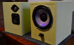
I'm going to the dark side - 2 way with only Caps, no nasty expensive inductors! Inspiration: shed full of odd drivers, every time I try to give my creations away to the kids, they say 'It's too big". So these are random drivers in a tiny 6L sealed box, the too small box adds a bass hump. They sound surprisingly OK, although a sprinkle of resistors would improve the balance a bit. Of course, this only works because of the massive difference in impedance between the W & the M - total Z is ~17 ohms, so inefficient.
Attachments
Yes.. to think it was once capacitors that were the dark horse and now it's iron. (I'm thinking earlier last century.)
I don't really see a case for inductors to be called "nasty & expensive".no nasty expensive inductors!
Depending on power levels, there is choice > from air core to iron core, even L with high DCR which can actually be useful in some situations.
As part of a whole speaker system, inductors are not necessarily expensive.
I have never built a crossover network that doesn't include at least one inductor.
I guess that with - drivers - impedance - efficiency and FLUKE, something decent could be created without them.
- Home
- Loudspeakers
- Multi-Way
- 2-Way with only 2 Inductors!