The structural diagram of the dual-channel 200W PWM DAC with ADAU1452 chip is shown below.

The board looks like this.

Measurement results, R load=4R, Vcc=48V.


Performance parameter PWM DAC:
The price of one board is 95 US dollars.
Shipping at my expense.
Only two boards are available.
A starter project for Sigma Studio is attached to the message.
The board looks like this.
Measurement results, R load=4R, Vcc=48V.
Performance parameter PWM DAC:
- Output power: 200 W per channel, with a 48 V supply and R load = 4 Ohms.
- Speaker impedance: 2 - 8 Ohm
- Frequency response: 20Hz - 20kHz
- THD: less than 0.005% on 8Ohm load, and less than 0.008% on 4Ohm load
- SNR: 105dB(A)
- Spdif Input : 16-32bit 44.1-96kHz
- Spdif Output : 16-32bit 44.1-96kHz
- I2S Input : 16-32bit 44.1-192kHz
- Power supply: DC 12V - 48V/ 5A-15A
- Consumption power: Idle mode 16W, sleeping mode 2.5W
- Efficiency - 83%
The price of one board is 95 US dollars.
Shipping at my expense.
Only two boards are available.
A starter project for Sigma Studio is attached to the message.
Attachments
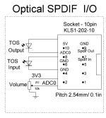
The board is compatible with input/output boards that also have a volume control potentiometer.
Board with coaxial input + $10.
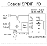
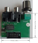
Board with optical input without ESP32 + $10.
Board with optical input and ESP32 + $15.
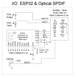
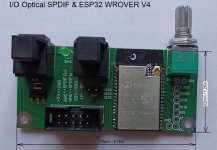
More information on using the ESP32 input board can be found here in post number 10.
https://www.diyaudio.com/community/threads/3-way-dsp-amp.415065/
Board with coaxial input + $10.


Board with optical input without ESP32 + $10.

Board with optical input and ESP32 + $15.


More information on using the ESP32 input board can be found here in post number 10.
https://www.diyaudio.com/community/threads/3-way-dsp-amp.415065/
Very interesting project!
Any board with analog input (which ADC?)? or only digital input?
Is there any speaker "thump" when switching on the amp+dsp?
What wattage is recommended for the PSU?
both channels are load independent? Can I power one woofer and one CD?? (200W is a little overkill for a CD).
Cheers!
Any board with analog input (which ADC?)? or only digital input?
Is there any speaker "thump" when switching on the amp+dsp?
What wattage is recommended for the PSU?
both channels are load independent? Can I power one woofer and one CD?? (200W is a little overkill for a CD).
Cheers!
I don't make ADC input boards, I haven't used analog audio outputs for a long time.Any board with analog input (which ADC?)? or only digital input?
If you need an analog input to this board, the board has an I2S input to which it is very easy to connect any ADC with an I2S output. For example, here is an ADC with an I2S output.
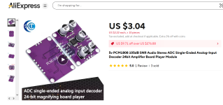
When turning this board on and off, there are no clicks at the output of the power DAC.Is there any speaker "thump" when switching on the amp+dsp?
But when programming ADAU1452, sometimes clicks are possible at the output of the DAC, this depends on the settings that are added to the ADAU.
If you want to have a stable 200W output for each channel, then the power supply must withstand a current of 800W/48V=17A.What wattage is recommended for the PSU?
If you want to have 200W output on a music signal, then the required power supply current can be reduced to 10A.
Both channels are independent from each other. If you do not really care about having 200W on the woofer, you can use such a board.both channels are load independent? Can I power one woofer and one CD?? (200W is a little overkill for a CD).
https://www.diyaudio.com/community/threads/3-way-dsp-amp.415065/
In another thread you've mentioned that this board can sustain 200W at 2 ohms (using TAS5162 and a high current choke). How much power can it produce with an 8 ohm load?
Both this and the 3x100W board seem really nice, BTW. Good work.
Both this and the 3x100W board seem really nice, BTW. Good work.
100W.How much power can it produce with an 8 ohm load?
Thank you.Good work.
A few additional questions:
what is the size of the PCB, and what is the size of the mounting plate?
If the amp would run at the maximum power, both channels driven, what radiator size is recommended for passive cooling in free air?
what is the size of the PCB, and what is the size of the mounting plate?
If the amp would run at the maximum power, both channels driven, what radiator size is recommended for passive cooling in free air?
The board size is 100mm by 70mm. The heat-conducting plate size is 120mm by 72mm.what is the size of the PCB, and what is the size of the mounting plate?
With a complex music signal and maximum volume, with both channels operating, heat losses will be about 50 W. The effective area of the radiator should be 1000 square centimeters.If the amp would run at the maximum power, both channels driven, what radiator size is recommended for passive cooling in free air?
From my calculation (ChatGPT), something like THIS should work. Correct?
@uriy-ch This is a GREAT project! CONGRATULATIONS! As soon as I get rid of some stuff I will surely buy a pair!
Now, If I might suggest something... please consider in making something with analog input and with 2 channels -1one more powerful (woofer) than the other (tweeter)- . Many of us would use this with the preamp outputs in out receivers (7+ channels), and as ridiculous as it could sound in the year 2025, there is no consumer device with 7+ digital outputs.
Yes, this radiator should be enough.From my calculation (ChatGPT), something like THIS should work. Correct?
@uriy-ch This is a GREAT project! CONGRATULATIONS!
Thank you.
As soon as I get rid of some stuff I will surely buy a pair!
I have only two of these boards assembled. When I will want to order components for assembling more of these boards, I don't know. These are the remains of a local special order. I think the achieved indicators are not very popular, for the power that few people need at such a price with such losses due to heat.
The principle of feedback operation in my DACs does not allow me to use TAS in SE+BTL mode. To be more precise, this can be implemented at the expense of significant deterioration of SNR and THD, in order to obtain more acceptable indicators, the chip must be used in PBTL mode.-1one more powerful (woofer) than the other (tweeter)- .
I don't want to go into the ADC area because it introduces additional problems when achieving high values.please consider in making something with analog input and with 2 channels
One way or another, the board itself can be connected to the ADC with an I2S output. Maybe sometime in the future, someone will check such a connection, but I'm not so interested in it because I have other more urgent tasks.
I suspect that the receivers have DACs with I2S input inside, i.e. if desired, you can intercept this stream and feed it to my DAC boards. After all my boards, these for DIY. Two 3-channel boards and one 2-channel board will give exactly 8 channels. But for this you will have to disassemble the receiver.Many of us would use this with the preamp outputs in out receivers (7+ channels), and as ridiculous as it could sound in the year 2025, there is no consumer device with 7+ digital outputs.