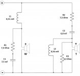
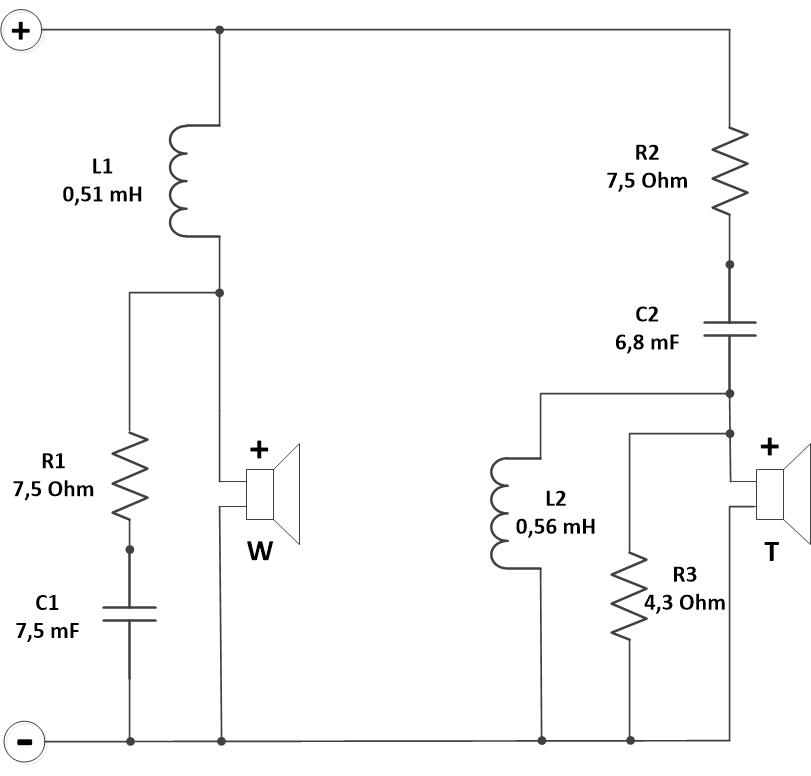
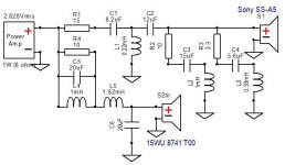
Hi to all. I am very new in DIY, but decided to make Scanspeak Lumine, as heard it at Youtube and was impressed by their clear sound. But as i already have 8-ohm tweeters (the ones from Sony ss-g55, 8 ohm, biocellulose), and decided to use 8-ohm version of SS 15WU8741T00, instead of 4-ohm 15WU4741T00 (mainly to avoid different impedance of tweeter and woofer). It seems that it will be something very different from the Lumine, but I hope that the woofer will give a good quality sound. Followed instructions in "Introduction to designing crossovers without measurement " thread, and made calculations, so I ended with the crossover shown. Can someone explain what is the role of R3 and L2 in the original Lumine crossover, and give advice on this crossover in general? Thanks in advance.
Attachments
Last edited:
R3 and L2, along with the drivers form the second branch of the respective filters, increasing order to three. What you've drawn do not use further branching and are therefore just second order filters. You have also forgotten to invert one of the drivers to compensate for the 180* phase shift between them.
Last edited:
I would advise rather to modify the original loudspeaker that you are using as parts donor. Its woofer seems worth exchanging for the one with better bass capabilities. A three way like that is superior to a lumine kit. There is a SS-G55 service manual available, and it appears to be an intelligent design.
Last edited:
Thank you both for advices! Unfortunatelly i already sold ss-g55, than bought just tweeters, as they are the best tweeters i ever heard - amazingly natural and fast. I also have a problem with a space, so going with something small 2-way bookshelf, in the size of Lumine, is the only option. That's why need to create some "Lumine-style" project, already purchased boxes and damping, but stucked at crossovers for now.
To make any kind of a simulation to help you with this project, first we need a manufacturer datasheet containing FR, Impedance and T/S parameters of the unknown tweeter, measures of an enclosure (and baffle). I don't know if you can find anywhere Sony specs, but these would either have to be measured or made up by guessing a lot. So in short, tell us exactly what parts (their specs) do you have right now.
YEah, Sony didn't published lot of info about these tweeters, the only information I was able to find about this tweeter is here (they are the practically the same tweeters - those used in ss-a5 and ss-g55: Measurements and compare | HiFiCompass
Cabinet dimensions are at: Lumine One 2-Way Speaker Kit.
Hope this can help some.
Cabinet dimensions are at: Lumine One 2-Way Speaker Kit.
Hope this can help some.
We are on it! 😉

Interesting problem.
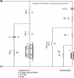
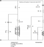
15WU4741T + XT25TG3004 Passive Crossover Design - Madisound Speaker PDF Library
But not hard.
Interesting problem.
15WU4741T + XT25TG3004 Passive Crossover Design - Madisound Speaker PDF Library
But not hard.
Btw, there is a difference in impedance between tweeters of ss-a5 and ss-g55, last ones i measured today - 8 Ohm. SS-a5 tweeters are 6 Ohm. So at least no need for impedance equalization in the crossover probably? Eh, wish to have some electrical background, to fully understand the roles of each passive element in the speaker crossovers.
I am not too worried about the tweeters. Can work with 6 ohms and 90dB.
Excellent woofers:
8741 https://www.scan-speak.dk/datasheet/pdf/15wu-8741t00.pdf
4741 https://www.scan-speak.dk/datasheet/pdf/15wu-4741t00.pdf
Bit lively at the top end around 5kHz. But nothing unfixable. But this isn't going to do it IMO:
You need second order on the midbass. Tame the breakup mode. Give us time.
Well, try changing 22(R4) in the original circuit to a higher value around 40. It's more or less the same curve, only with 6 ohms (vs 8).

For scaling LC filters according to changing impedance (8 ohms to 4ohms etc.), use R1/R2 = L1/L2 = C2/C1. New filter works for new load impedance, with the same cutoff frequency, Q factor and response.
All the best.
.. wish to have some electrical background, to fully understand the roles of each passive element in the speaker crossovers.
For scaling LC filters according to changing impedance (8 ohms to 4ohms etc.), use R1/R2 = L1/L2 = C2/C1. New filter works for new load impedance, with the same cutoff frequency, Q factor and response.
All the best.
Last edited:
Well, try simulating that. You may expect some changes because impedance is not exactly the same as resistance.
Last edited:
Unfortunatelly my knowledge in simulation software is almost zero, can you advice an easy program to start?
- Home
- Loudspeakers
- Multi-Way
- 2-way crossover with 15WU8741T00 advice needed