Hey guys!
I've bee building mesa boogie mark IIc+ clone for a while. Now I've completed all wiring job, turned it on and found that 1st stage (V1-a, see circuit diagram) is oscillating like hell at 50Hz (directly on pin 1). There also 50 Hz ~1V p-p distorted sine is present on the cathode of this stage (pin 3). Test signal - 200mV p-p sine from the signal gen into the input jack.
Here's an interesting part - I can eliminate the oscillation either by turning treble control all the way right or activating "Bass shift" function which just simple bypasses 15k resistor in the cathode circuit.
I tried to swap preamp tubes but result is still the same.
So any clues what can cause this problem?
Appreciate any help!
Circuit diagram:
https://app.box.com/s/fp7y3y7zetsj41vx5mz2o8s3veivesgj
PS. All power circuit after EQ works hunky-dory, so I just disconnect power amp input after the EQ stage.
PS. PS. Should mention before - V1 is on 12VDC filament supply.
Regards,
Phil
Last edited:
I don't know what your issue is, but couple of things here catch my eye.
Perhaps not related since you claim to get his effect with a test signal (you don't specify frequency!), but your input jack should be wired to connect the grid to ground when there is no signal. Also, while I see that you evidently have a ferrite bead in place on the grid, I would still install at least a small (10K should contribute almost no additional noise above the intrinsic noise of the stage) grid stopper right on pin 2. Admittedly, this is an issue normally with HF, but it is something I would do automatically. The lack of grid stoppers throughout the amp is a concern, even for the grid nodes fed nominally at fairly high output impedance.. you want at least small stoppers as close as possible to the pins.
Confirm that PSU node D is adequately decoupled from the rest of the PSU.. what is the corner frequency of the RC network for that node? Does the filter cap really measure the correct capacitance?
We have no information about your physical layout, but of course anything with mains frequency on it should be nowhere near your input stage.
Where is the amp getting its ground reference? This should ideally be right at the input stage.
If you disconnect the second grid (pin 7) do you still get the effect?
How clean really is your 12VDC? A poor DC supply can be worse than just using AC.
Oscillating at 50Hz is odd, by chance is that your line frequency? If so it's not oscillating it's picking up the AC input voltage somewhere.
Craig
Craig
2 Wombaticus : Yeah, I should add grid stoppers.. Testing frequency is 1 kHz.
Here's the PSU diagram:
https://app.box.com/s/nqc92si6zlfld4addul7xkmmn6pz5zwa
Cut-off frequency of the D node is 1/(2*Pi*1k*34uF) = 4.683 Hz.
I'll check filter cans.
All ac-mains stuff are located on the opposite site of the chassis
Ground reference is a star ground point near the PSU.
I'll try to disconnect input wire from the pcb and let you know if the problem will still present.
12VDC supply has 6800 uF before and 10000 uF after the regulator.
2 llwhtt: Oh yeah, this is a definitely mains frequency
I keep you poster the results. Also I'll make some gut shots for better visual understanding.
PS. This is my first amp build, so I appreciate your critics and advises.
Thanks!
10mF appears to be too high at the regulator's output. Try only 100µF. Perhaps too heavy cap triggers regulator's current protection.
Agreed. A 78xx regulator is typically happy with around 10uF. 10mF (10k uF) is huge. For regulators like this, more is not necessarily better.10mF appears to be too high at the regulator's output. Try only 100µF. Perhaps too heavy cap triggers regulator's current protection.
Agreed. A 78xx regulator is typically happy with around 10uF. 10mF (10k uF) is huge. For regulators like this, more is not necessarily better.
I'll second that as well. The datasheet value for output capacitance is only 100nF, although a bit more should be fine. But not 10KuF
Another issue with the PSU as shown is that capacitors that are stacked in series as you are doing should each be paralleled with resistors to ensure proper voltage sharing. You want to make sure that the current through the resistors significantly exceeds the leakage current of the caps. Something in the range of 270K - 470K should be about right.
Finally, why only 100nF for C3/ PSU node A? I can't imagine that you really intended to essentially have a choke input filter rather than a capacitor input filter! I don't know of any amps that actually use a choke input filter. Assuming that A is the node that you are using to feed the power tube plates, this value should be something more in the range of 47uF - 220uF depending on how stiff you like things.
Hah, actually 6.8 / 10 mF configuration I took from mesa mark V diagram
2 Wombaticus - there are 2x220uF Caps with two 220k/2W sharing resistors providing filtering for the node A.
Nope, heater supply is fine, here's some what I've done & found:
I've checked 1Meg input resistor in circuit and multimeter showed "open circuit", so I've made some modifications to the input jack and wire - I've disordered the resistor from the pcb and soldered 1Meg resistor directly to the jack and one more little wire to short the input when jack is unplugged. Also I soldered 10k 1/2w resistor at the end of shielded wire and soldered it directly to the tube input pin and added a 250p ceramic cap from grid to ground (it's been fitted at the place designated as "47p" (see pcb layout)). And and fixed the problem! But not completely..
I corrected tube pin numbers on the schismatic to match PCB layout (signal flow is V1-B -> V1-A -> V2-B -> V2-A for clean and V1-B -> V1-A -> V3-B -> V3-A-> V2-B -> V2-A for lead channel ):
[url=https://c1.staticflickr.com/5/4194/34567372816_50faa7f89f_o.gif]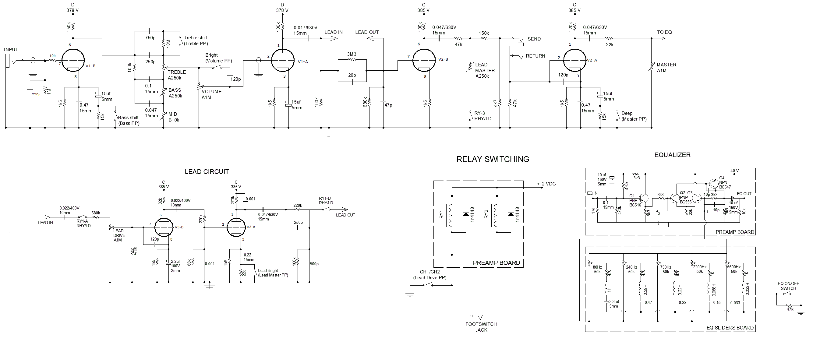 [/URL]
Preamp/Eq board actual layout (from SprintLayout):

12 V rail is fine. DC volts directly on pin 4 is 12.115, ac volts - 100uV rms.
Actual 12V regulator is LM1085-12 (I remember I got it in my parts drawer so I put it instead of 7812), So I corrected PSU diagram as well:

Now, DC volts at 1st tube:
Pin 6 - 217 VDC;
Pin 8 - 1.76 VDC;
Pin 1 - 257 VDC;
Pin 3 - 2.03 VDC.
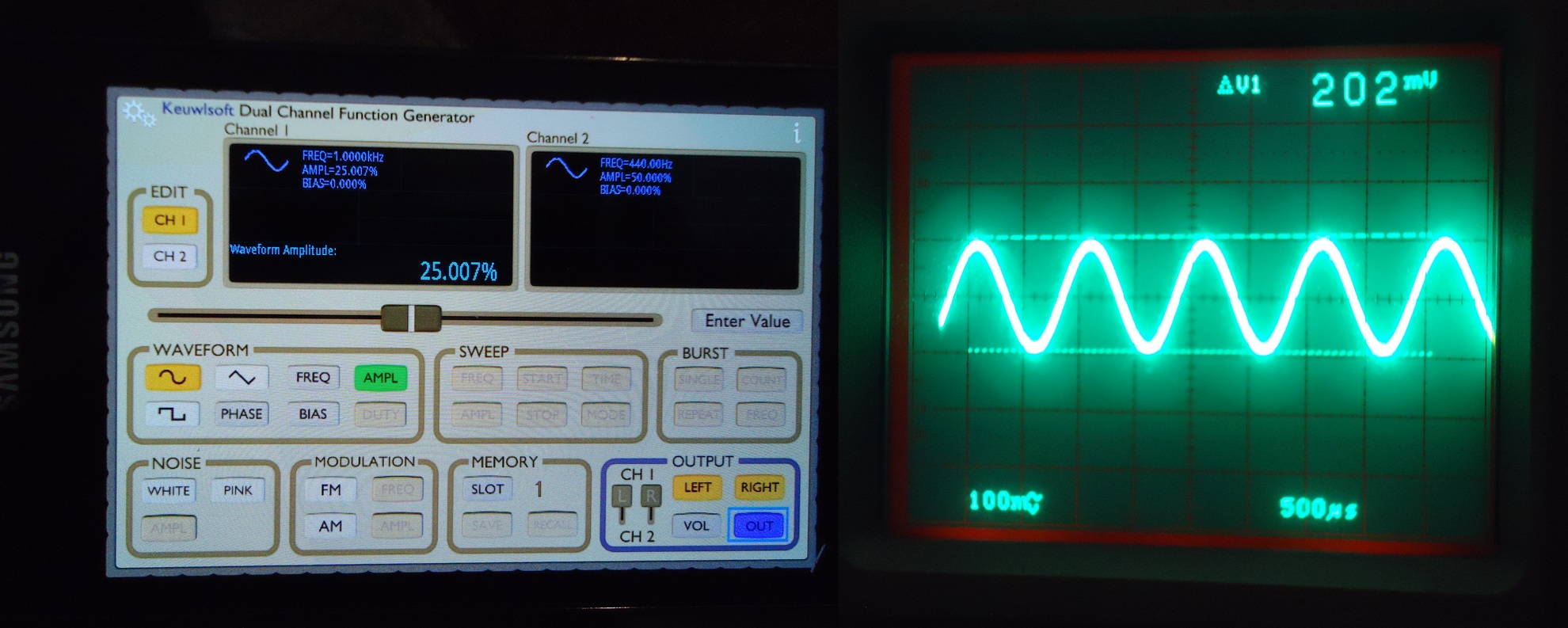
Here's my test signal generating via cellphone app (combined two shots - phone screen and scope waveform from the pin 7):
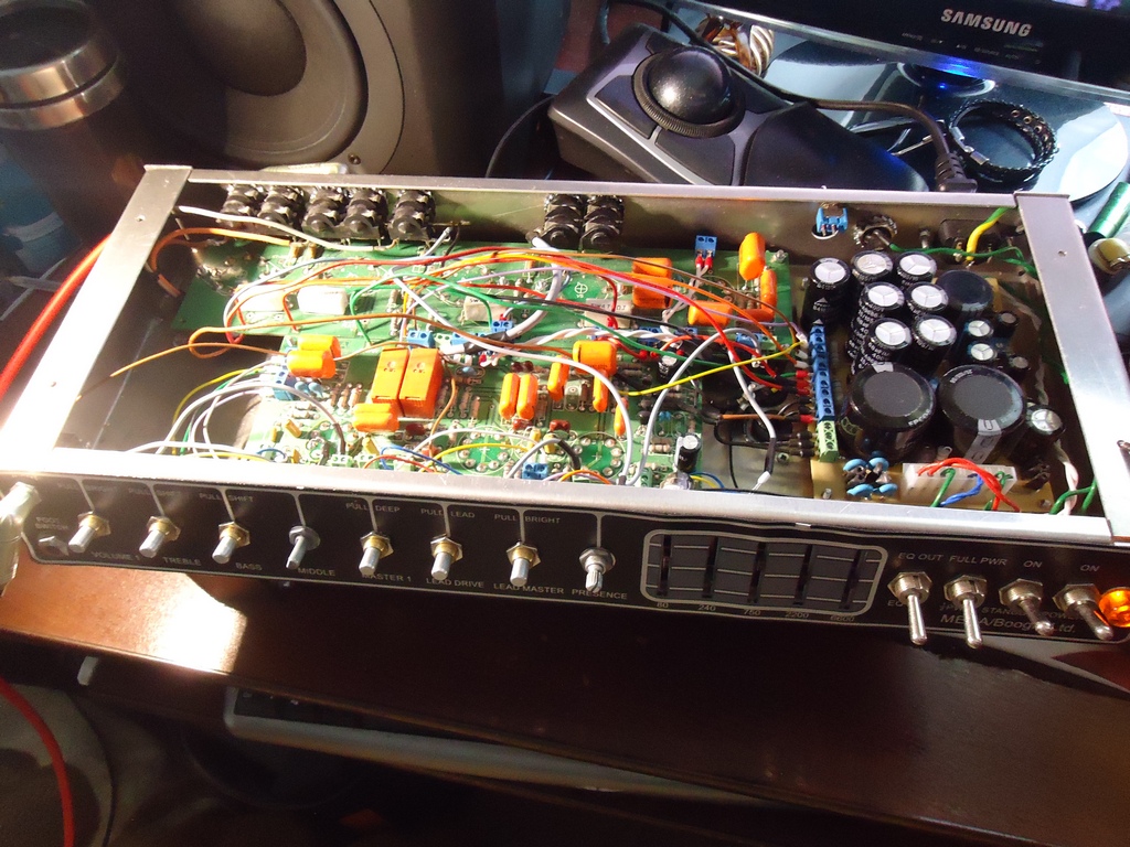
Overall gut shot (Power xformer - all way right, output xformer - all way lest left):
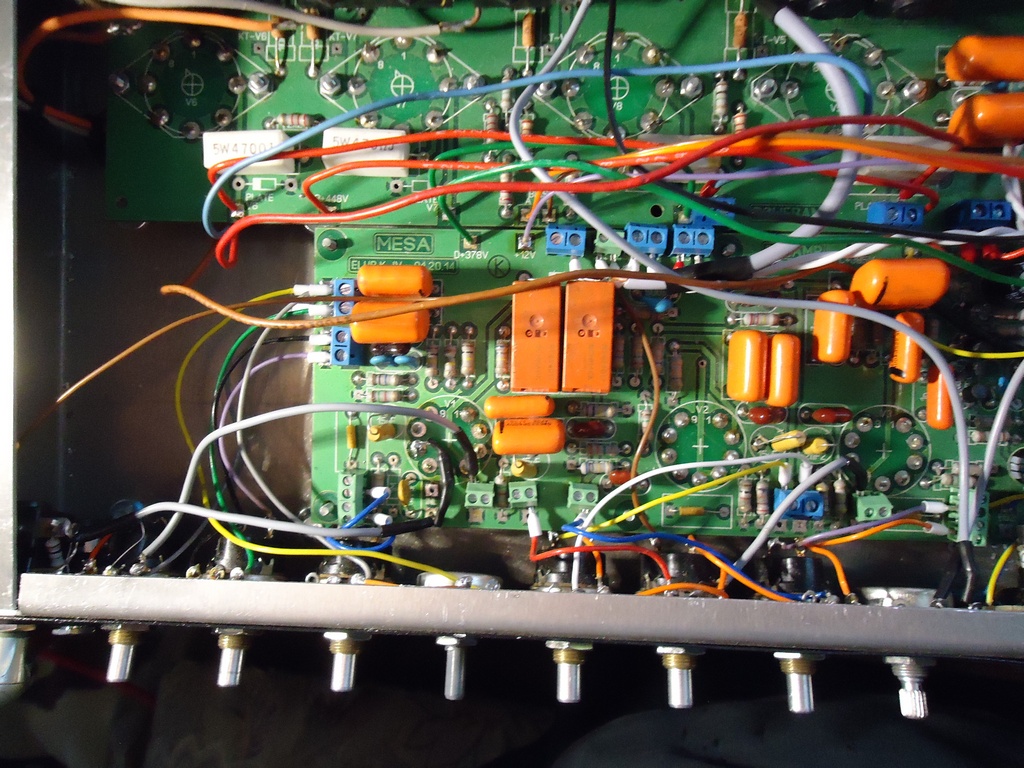
And preamp pcb (In bottom lest corner you can see input jack and 1M resistor):
So, back to the problem. Now I hot weird osculation at the pin 6 (first plate) even then the input is grounded (jack is unplugged), but frequency of oscillation changes with tone stack pots.
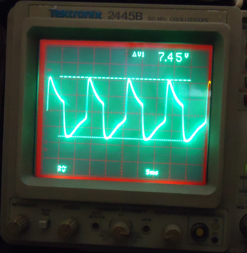
1st scope shot - no signal, input is grounded, volume pot all way up, bass and mid - 12 o'clock, treble pot all way down:
F = 83.3Hz, A = 75 Vp-p (it's 10x probe here):
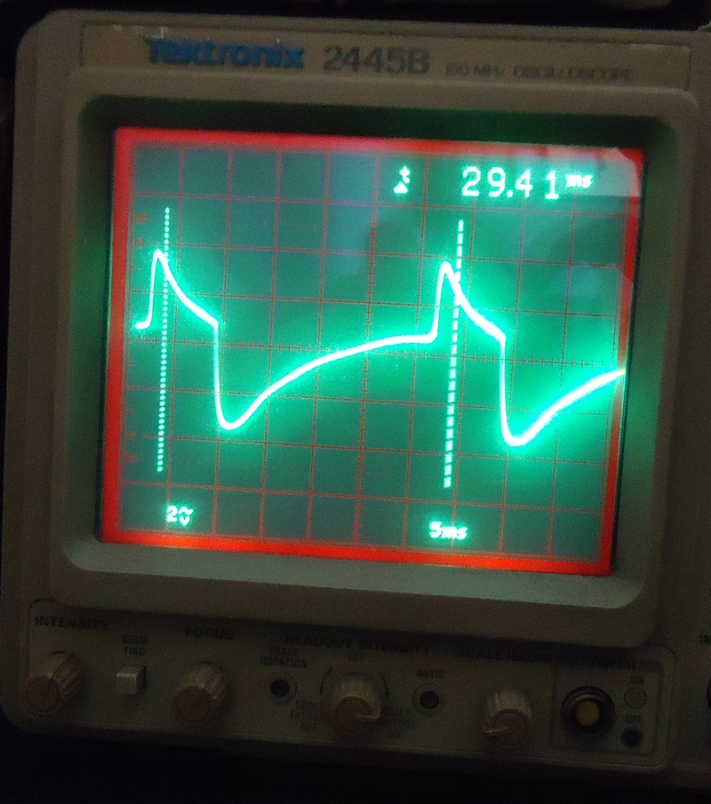
2nd scope shot - all settings the way, but bass all way up (right):
F=33 Hz, A = ~75 Vp-p.
And if I press hard on the face plate or TB pot shafts I can eliminate this oscillation.. Hmm.. Perhaps a bad solder joint or component?
Regards,
Phil
2 Wombaticus - there are 2x220uF Caps with two 220k/2W sharing resistors providing filtering for the node A.
Phil, was the concern offered on GroupDIY about not grounding the heater supply your mistake?
Nope, heater supply is fine, here's some what I've done & found:
I've checked 1Meg input resistor in circuit and multimeter showed "open circuit", so I've made some modifications to the input jack and wire - I've disordered the resistor from the pcb and soldered 1Meg resistor directly to the jack and one more little wire to short the input when jack is unplugged. Also I soldered 10k 1/2w resistor at the end of shielded wire and soldered it directly to the tube input pin and added a 250p ceramic cap from grid to ground (it's been fitted at the place designated as "47p" (see pcb layout)). And and fixed the problem! But not completely..
I corrected tube pin numbers on the schismatic to match PCB layout (signal flow is V1-B -> V1-A -> V2-B -> V2-A for clean and V1-B -> V1-A -> V3-B -> V3-A-> V2-B -> V2-A for lead channel ):
[url=https://c1.staticflickr.com/5/4194/34567372816_50faa7f89f_o.gif]
 [/URL]
Preamp/Eq board actual layout (from SprintLayout):
12 V rail is fine. DC volts directly on pin 4 is 12.115, ac volts - 100uV rms.
Actual 12V regulator is LM1085-12 (I remember I got it in my parts drawer so I put it instead of 7812), So I corrected PSU diagram as well:
Now, DC volts at 1st tube:
Pin 6 - 217 VDC;
Pin 8 - 1.76 VDC;
Pin 1 - 257 VDC;
Pin 3 - 2.03 VDC.
Here's my test signal generating via cellphone app (combined two shots - phone screen and scope waveform from the pin 7):
Overall gut shot (Power xformer - all way right, output xformer - all way lest left):
And preamp pcb (In bottom lest corner you can see input jack and 1M resistor):
So, back to the problem. Now I hot weird osculation at the pin 6 (first plate) even then the input is grounded (jack is unplugged), but frequency of oscillation changes with tone stack pots.
1st scope shot - no signal, input is grounded, volume pot all way up, bass and mid - 12 o'clock, treble pot all way down:
F = 83.3Hz, A = 75 Vp-p (it's 10x probe here):
2nd scope shot - all settings the way, but bass all way up (right):
F=33 Hz, A = ~75 Vp-p.
And if I press hard on the face plate or TB pot shafts I can eliminate this oscillation.. Hmm.. Perhaps a bad solder joint or component?
Regards,
Phil
Last edited:
- Status
- Not open for further replies.
- Home
- Live Sound
- Instruments and Amps
- 1st stage of the tube amp is oscillating 50Hz.