Does any one have the schematic for what I believe to be the first generation "The Punch 75 Rev F"?
The one I purchased has been messed with to a great extent, to the point of the addition of parts not stock to this unit. Any help would be greatly appreciated. This unit does take the 2N6488 and 2N5490 outputs. The power supply uses 2) D44VH10's.
The one I purchased has been messed with to a great extent, to the point of the addition of parts not stock to this unit. Any help would be greatly appreciated. This unit does take the 2N6488 and 2N5490 outputs. The power supply uses 2) D44VH10's.
I remember that one. Pre mosfet Punch amp.
Simple amp inside but post a internal picture to jog everyone's memory please? I don't have a schematic perhaps someone does. But I do remember them pretty good. 6488 and 6490 outputs, 500K and 5 K ohm bass & treble gain pots, and little PCB trim pots for gains. 6488 can replace D44VH10 power supply transistors....Pictures help a lot if you can....😉
Simple amp inside but post a internal picture to jog everyone's memory please? I don't have a schematic perhaps someone does. But I do remember them pretty good. 6488 and 6490 outputs, 500K and 5 K ohm bass & treble gain pots, and little PCB trim pots for gains. 6488 can replace D44VH10 power supply transistors....Pictures help a lot if you can....😉
Here is an image of the unit I have. It's possible it still works, I have not fired it yet. There has been lots of parts replaced and addition of parts I believe don't belong. So far the parts I have checked are still good. I would still like the schematic for verification reasons.
Attachments
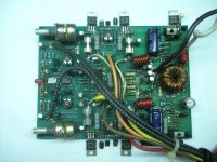
Well I have seen worse. Looks as though someone went about replacing some of the smaller power supply transistors < MPSA06 and MPSA56 >. No blown fuses is a big plus but be aware that this amp needs fuses in the speaker leads to protect your speakers. people like to cut them out but when these amps fail a channel they allow the rail supply to go directly to the speakers, so if the speaker hot lead fuses are missing please add them.
These amps also used epoxy rectifiers < those white with blue markings diodes, 4 of them two on each side of the supply > They tend to desolder themselves from excessive heat build up , as they run real hot under heavy loads. Perry Babin had a thing where he replaces them with ultra fast modern TO-220 devices that I think is just novel. It solves problems these amps tended to have in that area. You might look up his links under any of his thread posts here on this forum section, and visit his training web site. I believe he has a section on modding this series for better reliability.
Also I would replace the big blue caps as they have probably seen better days with this amps age and what not. They filter and store the amps energy, so it will help restore SQ.
Also do not operate this out of the sink unless you have the bias pots located dead center of the output on each side turn all the way down. This amps bias can cause the power transistors to run warm to hot without proper sinking and it will fail the amp in a just a few minutes without the sink in place. Lucky you this series the sink was coated with a black anodizing that also was non conductive so no insulators are needed with this amp if the coating is intact and undamaged. < just need some heat sink compound underneath the power devices >
This was one of RF's simpler amps, no complex IC controlled power supply. And a dual op-amp is used as the input circuitry for each main amp section. So unless you have leaky or failed transistors the only real possible reason for high DC offset on the output would be the op-amp input chips located dead middle of the board in between the main amp channels.
If I may suggest, if I were you, I would reassemble the amp back into its sink, and apply 12 volts to it and see if it operates < the red led up front will light up > and then check each set of speaker leads for any DC voltage on them with your DVM. Let me know if you find anything above 0.005 volts DC or 5 milli-volts DC. I can make suggestion based on this info as to where any issues might be. I used to call these easy money amps long ago, due to their simplicity, and low cost parts. The only tough items to find are those bass and treble gain pots. I have a set left NOS from 1991, and oh their original knobs and I have a few of those around also. The driver transistors are the ones with the little metal tab on top of them, I have those also, and they can be found in the bay area also if need be. I can tell you where if you need them original and NOS.
Well let me know what you find testing...😉
PS if the supply wont operate I found that those two power transistors marked D40D8 tended to fail a lot. They are the ones in the supply area on the board with their metals tabs bent over. NTE replacements can work for these, but I think I have a few laying around if you can't find them using Findchips.com, or octopart.com parts search engines...
Last edited:
Well I have seen worse. Looks as though someone went about replacing some of the smaller power supply transistors < MPSA06 and MPSA56 >. No blown fuses is a big plus but be aware that this amp needs fuses in the speaker leads to protect your speakers. people like to cut them out but when these amps fail a channel they allow the rail supply to go directly to the speakers, so if the speaker hot lead fuses are missing please add them.
These amps also used epoxy rectifiers < those white with blue markings diodes, 4 of them two on each side of the supply > They tend to desolder themselves from excessive heat build up , as they run real hot under heavy loads. Perry Babin had a thing where he replaces them with ultra fast modern TO-220 devices that I think is just novel. It solves problems these amps tended to have in that area. You might look up his links under any of his thread posts here on this forum section, and visit his training web site. I believe he has a section on modding this series for better reliability.
Also I would replace the big blue caps as they have probably seen better days with this amps age and what not. They filter and store the amps energy, so it will help restore SQ.
Also do not operate this out of the sink unless you have the bias pots located dead center of the output on each side turn all the way down. This amps bias can cause the power transistors to run warm to hot without proper sinking and it will fail the amp in a just a few minutes without the sink in place. Lucky you this series the sink was coated with a black anodizing that also was non conductive so no insulators are needed with this amp if the coating is intact and undamaged. < just need some heat sink compound underneath the power devices >
This was one of RF's simpler amps, no complex IC controlled power supply. And a dual op-amp is used as the input circuitry for each main amp section. So unless you have leaky or failed transistors the only real possible reason for high DC offset on the output would be the op-amp input chips located dead middle of the board in between the main amp channels.
If I may suggest, if I were you, I would reassemble the amp back into its sink, and apply 12 volts to it and see if it operates < the red led up front will light up > and then check each set of speaker leads for any DC voltage on them with your DVM. Let me know if you find anything above 0.005 volts DC or 5 milli-volts DC. I can make suggestion based on this info as to where any issues might be. I used to call these easy money amps long ago, due to their simplicity, and low cost parts. The only tough items to find are those bass and treble gain pots. I have a set left NOS from 1991, and oh their original knobs and I have a few of those around also. The driver transistors are the ones with the little metal tab on top of them, I have those also, and they can be found in the bay area also if need be. I can tell you where if you need them original and NOS.
Well let me know what you find testing...😉
PS if the supply wont operate I found that those two power transistors marked D40D8 tended to fail a lot. They are the ones in the supply area on the board with their metals tabs bent over. NTE replacements can work for these, but I think I have a few laying around if you can't find them using Findchips.com, or octopart.com parts search engines...
Hi, don't mean to interrupt but I have two RF amps same era as this one. One being a Punch 150 with a bad channel with rail voltage on speaker leads just one channel. And second a Punch 45 I got it super like 5 dollars was tooken apart but would like to get up and working. I have a thread up for the RF 150 I'm working on. Thanks guys
Powered up, practically no DC on outputs. Rail good. Signal a little quirky, signal taken at op amp outs, had like a triple sine wave, input at 100 hz. Looked at output sine looked fine and clean. Hooked to resistor block, took to over 10 amps and signal clipped evenly. Sound is good. I still do not know why external parts were added!
Any thoughts anyone.
Richard
Any thoughts anyone.
Richard
Ironic. I just got one of these in the shop today. 3 out of the 4 fuses are blown. And the outputs are not shorted.
Gotta order up those specialty fuses, and then see whats up.
Gotta order up those specialty fuses, and then see whats up.
Powered up, practically no DC on outputs. Rail good. Signal a little quirky, signal taken at op amp outs, had like a triple sine wave, input at 100 hz. Looked at output sine looked fine and clean. Hooked to resistor block, took to over 10 amps and signal clipped evenly. Sound is good. I still do not know why external parts were added!
Any thoughts anyone.
Richard
Back when this was made amp manufactures did not scrap boards because of small needed circuitry mods, they just added them hard wire style. So don't let some of what you see worry you too much unless the amp is not meeting its potential. Everyone in Arizona was known for small add on mods back when this amp was new. And that includes PPI, Orion, ADS, Rockford, etc... even Zapco did some back then...That is why you see similar amps with different REV numbers on them for the same amp. But to prevent waste and profitability loss almost all the big names added circuitry mods as needed to older board designs. It just saved money back then, and made sense to them business wise back then....
Since there is a lot of work that needs cleaning up, I might as well refresh the caps, possibly the rectifiers and the power supply outputs, they have been movement stressed. The wiring harness also needs replacing. I think well worth the time for such a prize from Rockford. Very powerful for such a small amp. It could blow the cones right out of your speakers if not careful.
Thanks for the info 1moreamp.
Richard
Thanks for the info 1moreamp.
Richard
I always upgrade the wiring for the power and ground to the larger power 300 size. I have power300 and power650 factory power/ground/fan harnesses in stock. PM if you need one.
Thanks Sean, I do have one left, and bulk hot and ground wire. Little guy has been playing out on the bench, while I'm working on a 150HD. Nice little unit.
Glad I can hear from you time to time. Might need some hard to get parts for these old guys. Take care Sean.
Richard
Glad I can hear from you time to time. Might need some hard to get parts for these old guys. Take care Sean.
Richard
Since there is a lot of work that needs cleaning up, I might as well refresh the caps, possibly the rectifiers and the power supply outputs, they have been movement stressed. The wiring harness also needs replacing. I think well worth the time for such a prize from Rockford. Very powerful for such a small amp. It could blow the cones right out of your speakers if not careful.
Thanks for the info 1moreamp.
Richard
Glad its working out for you🙂 I'm just down the road a piece from your location. Always glad to help...😉
I'm always glad to help out and hear from you guys on the forum. I know I have received much help from others on the forum. I am very busy but when I can I always try and offer help.
I have a question for the rectifiers in a 1st gen punch 45 mosfet. What can I use to replace the old rectifiers? Two of them are cracked. Thanks guys!
The part number should be on the other two on the opposite side. All four are the same device just depends on where you point the anode and cathode. As I recall they were all not that big current rating wise, but its been a while since I have seen them so brain fog prevents me from posting the exact part numbers.😱
But, if your up for a mod, Perry uses some Motorola / On ultra fast to-220 style replacements that IMO work much better then the original epoxy rectifiers. Check his web site for that mod, I am sure I saw it there some time ago, or search this forum as I know he posted it in a thread once before also, with a picture also..😉
But, if your up for a mod, Perry uses some Motorola / On ultra fast to-220 style replacements that IMO work much better then the original epoxy rectifiers. Check his web site for that mod, I am sure I saw it there some time ago, or search this forum as I know he posted it in a thread once before also, with a picture also..😉
The mods to the punch 45 are on this site. Excellent modification, I have done it before. Thanks Perry!
Basic Car Audio Electronics
Basic Car Audio Electronics
- Status
- Not open for further replies.
- Home
- General Interest
- Car Audio
- 1st generation Punch 75