Hello:
I own a 1979 Pro Reverb. When I got it the owner had just had a complete cap job done at a reputable place. But he had installed a set of 5881 power tubes. I am told these tubes will not handle the ultra linear setup on this amp. It was barely making sound when I got it. I opened it up to find both power tube sockets baddly burnt. I replaced the socket with new ones and I installed a set of NOS Sylvania 6l6gc-str tubes.The clean channel sounds great but the vibrato channel breaks up with a nasty flubby distortion at about 3. I have spent a lot of time checking parts and I can't seem to find the problem. I have replaced cathode bypass caps and resistors. I have replaced all filter caps and coupling caps.I bought a tube tester and made sure all preamp tubes were good.It also crackles anytime you move the master volume pot. The bias chekc right on both power tubes...-36ma...I also replaced v4 tube socket.
Any help would be appreciated...I'm out of ideas....
The crackling resulting from adjusting the vibrato channel volume control could be an indication of DC present on the pot; possibly caused by a leaky capacitor in the tone stack. Next guess would be something to do with the vibrato (actually tremolo) circuitry---try bypassing that.
The Master vol pot is fed from both channels. Check the cap from the plate of the 3rd stage (reverb output + dry combining stage) in the Vib channel for DC leakage. A dirty pot can cause crackle but often can be resolved with several rotations back and forth.
I'm assuming the schematic since it is not posted.
I'm assuming the schematic since it is not posted.
Try cleaning the Vibrato-Pedal switch. I've had cases where a faulty switch was acting as a high-impedance path (causing ringing in an amp).
--
Stephan
--
Stephan
I don't have the pedal hooked up. I checked all the pots on the vibrato channel. They all show from 8 to 14 mv DC.
I decided to try and localize the problem by pulling tubes. I started at V1 and checked for dc voltage at the master volume after each pull. Then I reinstalled each in the same order. The dc voltage on the master volume only disappears when I pull V6 , the phase inverter tube.
> master volume pot and it shows 70 VDC
> The dc voltage on the master volume only disappears when I pull V6
So the cap from MasVol to V6 is leaking.
Also makes sense because it goes to +110v through a large resistance. When V6 is yanked, 110V falls to zero. (This argues *against* leakage from V1 V4 plates, which would go toward 365V when yanked.)
Attachments
I could find only 2 caps inline from the master volume to V6. a .1uf 200v and a .01uf 1kv. I replaced them both . No change at all. still same problem.It's a shame because the normal channel sounds great , but the vibrato channel has flubby distortion at 3 and the master volume still crackles loudly when turned.
I did find something interesting. I was measuring voltage on all the cathode caps. The one on V5 is supposed to read 1.8V according to the schematic. Mine is reading 4.62V.
link to a better resolution schematic:
http://schematicheaven.net/fenderamps/cbs_70w_mstrvol_pullsw_super-pro-bmstr_rev.pdf
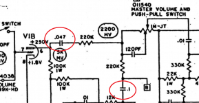
your suspects for DC voltage in the master pot are these two:

check for DC voltage after each one of them.
however i don't think it's related to the vibrato channel problem.
reading 4.62 on V5 cathode is a good bet for the problem.the tube is not biased correctly and can cause problems,replace the cathode cap and resistor on V5.
see how it goes from there🙂
http://schematicheaven.net/fenderamps/cbs_70w_mstrvol_pullsw_super-pro-bmstr_rev.pdf
your suspects for DC voltage in the master pot are these two:
check for DC voltage after each one of them.
however i don't think it's related to the vibrato channel problem.
reading 4.62 on V5 cathode is a good bet for the problem.the tube is not biased correctly and can cause problems,replace the cathode cap and resistor on V5.
see how it goes from there🙂
Attachments
Well 1 step forward 1 step back...lol I found 5VDC on the back side of the .01uf cap you suggested checking. I pulled everything at both legs of the cap , cleaned it all up and put it back together. No more crackle , no more leaking voltage , but now the vibrato channel has almost no volume. I set all controls to 5 . The normal side will rattle the walls , but the vibrato channel is as if the volume were on 1. Still getting odd readings on the cathode caps. V1 - 1.9 , V2a - 1.4 , V2b - 1.5 , V4 - .53 , V5 - 0.0. guess I'm gonna have to buy some 25uf 25v caps..
it looks like the culprit is V5. if you get 0 VDC on it's cathode you won't get alot of sound out of it.
it means this tube is not doing any work.
and since it is responsible for the vibrato intensity & speed i think it might be it.
you can see it connects after the coupling cap of V4B(the one you fixed) to the master pot(the B mark).
replace the cathode bypass caps and check for cold solder joints there.
also check the resistors value.they may stray away from their original value.
I just measured plate voltage , [pins 1 and 7 ] on V4. they both show negative volts in the millivolts range. they are supposed to show +250v...definetly something wrong there.
I replaced the .003uf cap. I measured the voltage on both sides of the .003 cap...360VDC on the back side....-68MV on the other , which wires directly to pin 1 on V4 . shouldn't I be showing the 250VDC plate voltage on the side that's showing -68MV ?
Last edited:
pin 1 on V4 should show 250VDC pin 7 on it is the grid, so -68mv is ok.
as for the .003 cap, the side that connects to the tube plate should have high DC on it and the other side shouldn't. so it's ok.
that's what this capacitor's purpose. to filter out DC voltage from the audio signal AKA coupling cap.
in order to see what's going on, create a sheet in excel or something similar.
write down all the voltages on all the pins of all the tubes.
this way you can see where the problems starts😉
My .003 cap does just the opposite of what it should. It shows 360VDC on the back side and shows - MV's on the side that connects to V4-1 . That's my problem. trying to figure why it's backwards. I replaced the .003 cap with a new one , but it made no difference. The back side of that cap shows 360VDC and so does the outside post on the reverb pot...All my voltages are correct until you get to V4. Then V4 and V5 are all wrong.
- Status
- Not open for further replies.
- Home
- Live Sound
- Instruments and Amps
- 1979 Pro Reverb problem