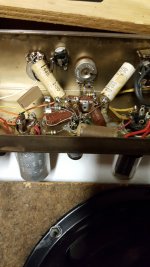
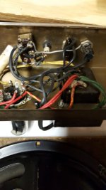
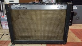
I am reworking a previously non-functional Harmony H415 1966 model. Replaced all caps and out of range resistors. fires up ok and is pretty quiet after warmup with no signal. However the B+ voltage is 50V higher (370v) than the schematic (320v). this has the plate voltage over the rated max for the JJ-EL84 / 6BQ5 power tubes. OK - So i tried to adjust the BIAS after much research and decided to change the 5W 130 ohm bias resistor to 180 ohm - based on some calculations however the following happened.. The Cathode voltage - pin 3 in this case (6BQ5) was 11.25 with the original 130 ohm resistor. AFTER changing the resistor to 180 ohm the Cathode voltage simply rose to 13.92v and the plate voltage increased on both tubes therefore the WATTS remain at 14W average 110% for these tubes. They will not last over loaded like this. New to this vintage point to point wired tube stuff, but experienced otherwise.
I will attach a schematic..
I hope to lower the B+ output voltage using a mod if anyone can help with that.
Also hope to understand the bias thing... why it did what it did.
Thanks in advance!
I will attach a schematic..
I hope to lower the B+ output voltage using a mod if anyone can help with that.
Also hope to understand the bias thing... why it did what it did.
Thanks in advance!
Attachments
Found part of my own answer for the bias change. The voltage adjusted as the current changed, watts remained near the same. My B+ is 50V too hot across the board, it has the old 5Y3GT rectifier tube. It is good according to specs, I would rather mod than replace the tube at this point it has cost me more than expected nickle dime stuff adds up and the preamp tubes had to be replaced and i got 2 matched JJ EL84 / 6BQ5 but they were not cheap. I spent the most on a new filter multi cap can for it. the old one was total fail and I wanted to keep it as vintage as possible... On the low voltage circuits i usually work with I could just use 2 resistors to control the voltage, or zener diode. This old amp circuit seems very basic and I don't want to change it any more than necessary. Possibly R25 or R26 could make a difference R25 was replaced with new already. Thanks again.
What is your filament voltage? Chances are your entire secondary is putting out higher because of today's higher wall voltage. If that is the cause, look up bucking transformer. Or there are other ways to reduce the b+.
Yeah, line voltage is about 13% higher these days, maybe more.
Just increase the value of the plate resistor, or put two in if there is not any after the push pull transformer. For a 10W resistor, a little more than a dollar is a lot cheaper than a bucking transformer. You could mount it on a cinch terminal strip to get it up in the air. Another dollar. Or if hot filament voltage bothers you, (not as life shortening as red plate) put a $3 resistor in the transformer primary to get the input to the transformer back to 110 vac.
Just increase the value of the plate resistor, or put two in if there is not any after the push pull transformer. For a 10W resistor, a little more than a dollar is a lot cheaper than a bucking transformer. You could mount it on a cinch terminal strip to get it up in the air. Another dollar. Or if hot filament voltage bothers you, (not as life shortening as red plate) put a $3 resistor in the transformer primary to get the input to the transformer back to 110 vac.
Assuming the voltages you mention are with the amp plugged into the wall, not a variac set at 117v, I'd suggest the following mod . . . add an RC section between the first cap and the CT of the output transformer and before R25. R should be ~600 ohms. Since it will be dissipating ~4.2w, I'd use one rated for 20w. A 10w part will work but will get pretty hot. For the C, I would use a separate cap mounted under the chassis, maybe a 22 or 33uf (common modern values). This should drop the overall voltage ~50v - I'm assuming an overall current draw of ~83mA. You may still need to add a small value resistor (less than 1 ohm) to the heater supply depending on what voltage you're getting there.
While the 5Y3GT data sheet recommends only 20uf be used for cap input, the stock 40uf should be OK since you are drawing less than the maximum current allowed. I'd suggest keeping an eye on the 5Y3 to see if there is any arcing on startup. If that concerns you, swap the existing 40uf cap with the 22 or 33uf cap suggested above.
If you need to order parts and the shipping charges are eating you alive, here's a tip . . . Digi-Key ships free if you send in your order by mail, instead of ordering online, and pay using a personal check or money order. See, Terms and Conditions on their website.
Last edited:
Add another R and C. Drop and filter.
You are probably also running the heaters on the high side of 6.3V. Maybe 7V. Heater failures from mild over-volts are rare, but this is getting to the extreme of "mild", to where we used to kill TV tubes (series string). An alternative is a 120V:12V 1A transformer, the leads scrambled to make it nominal 120V:108V auto-transformer. This will make 120V-125V into old-style "110V".
You are probably also running the heaters on the high side of 6.3V. Maybe 7V. Heater failures from mild over-volts are rare, but this is getting to the extreme of "mild", to where we used to kill TV tubes (series string). An alternative is a 120V:12V 1A transformer, the leads scrambled to make it nominal 120V:108V auto-transformer. This will make 120V-125V into old-style "110V".
Attachments

Thanks for your help! Since OP I replaced several out of range resistors, (there was a kind of hiss static randomly cycling and read that likely cause was the old resistors). This made the tremolo function correctly. It also brought voltages across the board back to the expected high as a result of the higher line voltage. I checked the heater AC voltage leg and it is 6.5 vac after warm-up. The amp sounds great with the exception of over wattage breakup/clipping after vol is set to around 4/5. I still have some random static hiss but even that is not too bad. I did not replace all the resistors but it could be from the old pots. I cleaned them but they are the originals. I was really hoping to keep those in play. I used a non-lube cleaner but i have some tuner cleaner somewhere I have to find where i put it LOL. I think I may use the 50W 600ohm mains resistor method. There is a spot beside the transformer I can place it and i can fashion a mount that I can use the transformer bolt to hold in place. (do not want to drill any new holes)
Thanks again, I will post a couple of pic's later...
Thanks again, I will post a couple of pic's later...
I have to calculate a power resistor value that will make my line voltage 110v.
600 ohm is too high i think. My line voltage in this area is 120vac. My transformer winding resistance is 6.6 ohm. It draws 0.735 Amp after warm-up. (it has a 2 amp fuse so i removed it and connected my Fluke to get actual amp draw.) Using ohms law calculator I am seeing 110 v - 0.735 A = 149.65986 ohm - 80.85 W ok when 120V - 0.735 A = 163.26531 Ohm - 88.2 W, so does that mean i need a 14 OHM 100 w POWER RESISTOR?? I see 8 and 10 ohm available then they jump up to 100ohm and 150 ohm. I assume I can just get close, but am i even on the right track?
Thanks.
OK so i'm a little impatient so I did some more searching and decided to try this with parts i have on hand. i put a 20 ohm 20 watt ceramic wire wound chassis mount resistor in the line just after the fuse. I only needed to use up 10 volts so I figured this would work. I actually thought it would make the volts a bit low but here is the result. pin 8 / 5Y3GT is now 315 V. Plate volts are 290 and 310. Bias resistor Voltage is 10.8 v. AVERAGE for both tubes is 12 Watts. Red plating in center now gone. Heater voltage is now 5.9 vac. Everything seems to have dropped right into the spec for the schematic. Random mystery hiss is also gone, it is quiet as a church mouse. ONLY additional concern is that I didn't bolt the power resistor to the chassis yet so it was pretty hot to the touch but not blistering. I would rather have had a 40 or 50 watt rated one but I think with the metal of the chassis working with it should be acceptable. I found a formula for figuring the resistor needed and the power dissipation. For Resistor value try - R = (Vt - Vi) / I in this case 120 - 110 = 10 then 10/.735 = 13.60 or round 14 Ohms. Now to get the power rating use P = (Vt - Vi) X I in this case 120 - 110 = 10 then 10 X .735 = 7.35 watts to dissipate. I used a 20W because a 10 watt would have been pretty hot for sure. Not as energy efficient as modern desires but effective in this case. I'm just glad I had the resistor on the bench already. I will update a bit later... thanks again!!
I would not fret about 6.5V, just 3% high.
I don't follow your math. 100W seems unlikely since the whole amp is likely to be less, and we only need a small drop. I get like 13 Ohms at 8-ish Watts. I would buy a 10 Ohm 20W part.
I don't follow your math. 100W seems unlikely since the whole amp is likely to be less, and we only need a small drop. I get like 13 Ohms at 8-ish Watts. I would buy a 10 Ohm 20W part.
Last update for tonight. I hooked up to it and played for about 45min to see how it fared. I am very surprised at how good this thing sounds. I also noticed that unlike my modern and solid state amps I had a tremendous amount of control of the sound from my guitar. Ambiance is incredible. Tremolo was not as i expected (nothing like the digital stomp boxes) It was smooth and subtle. I didn't think it was working right but then i read about the old tube tremolos and they said the same. I do have a hiss sound still in one of the channels but listen to how i found it... I took a pointed stick (looks like a foot long corn dog stick to me) and tapped the old resistors gently.. WA-LA! I have 2 making sound when i tap then. I had no idea a resistor would do that but they do. (I read about that in another thread somewhere) Anyway i'm burnt out tonight so i will replace the 2 resistors tomorrow and I bet that channel clears up. I feel confident since BOTH resistors are in that channel's pre-amp chain.
The ideas you guys gave me got me pointed right direction so thank you very much, your input is appreciated.
The ideas you guys gave me got me pointed right direction so thank you very much, your input is appreciated.
I have to calculate a power resistor value that will make my line voltage 110v. 600 ohm is too high i think. My line voltage in this area is 120vac. My transformer winding resistance is 6.6 ohm. It draws 0.735 Amp after warm-up. (it has a 2 amp fuse so i removed it and connected my Fluke to get actual amp draw.) Using ohms law calculator I am seeing 110 v - 0.735 A = 149.65986 ohm - 80.85 W ok when 120V - 0.735 A = 163.26531 Ohm - 88.2 W, so does that mean i need a 14 OHM 100 w POWER RESISTOR?? I see 8 and 10 ohm available then they jump up to 100ohm and 150 ohm. I assume I can just get close, but am i even on the right track? Thanks.
Hi Doc - It sounds like you're trying to reduce the line voltage going into the primary of the PT. I think the better approach - as suggested by myself and PRR - is to reduce voltage on the secondary side. That's where I suggested using the 600 ohm resistor and an additional cap. PRR has attached a schematic showing where to add the new RC section. We have suggested slightly different parts values but the concept is the same.
I'm confused about your current readings too. If you measured cathode voltage on the 6BQ5s at 13.92v using a 180 ohm resistor: 13.92 / 180 = .0773 (77.3 mA). I guesstimated an additional 6 mA for the other tubes to come up with the 83 mA overall figure I used earlier. The figure you claim to have measured - 735 mA - is way too high for an amp like this. If your tubes were really drawing that much current they would be burned to a crisp instantly. I thought you might have a simple math error and the actual draw is 73.5 mA, but that doesn't square with your earlier measurement of 77.3 mA which only included the 6BQ5s. The total draw would be higher for the overall amp since there are other tubes drawing current.
Assuming I'm close on the current draw, here's the math I used to determine the resistor value: R = 50v (desired drop) / 0.083 A = 602.4 ohms. As I mentioned, the dissipation would be just over 4w so while a 10w resistor would work, it will get pretty hot so I'd suggest a 20w part since I prefer to derate by a factor of 5. Your heater voltage is well within spec, so no resistors needed to drop it.
After you get the B+ voltage down near what's shown on the schematic, you may want to try going back to the original cathode resistor value.
Last edited:
After you get the B+ voltage down near what's shown on the schematic, you may want to try going back to the original cathode resistor value.
Sorry for the confusion... just for clarification, I have to wait after i post for a moderator to approve the post. I continue to use several other forums as well as doing research thru searches of existing posts. I actually found my own answers to my questions during the wait times. The responses got me pointed towards doing the right searches and as a result i found my solutions.
I had long ago put the original spec 130 ohm 5w bias resistor back in. Yes the voltages were WAY to high. I also found an imbalance due to several old resistors, they checked within allowances but were failing under load apparently. (a vintage radio forum had a similar issue and there was a tell tale hiss) After replacing all the bad resistors everything fell into balance except for the overall voltage being too high still and tube were still at 14 watts.. current was around 46 ma if i remember voltages were still hitting 355 vdc at the plates 343 vdc actual.
My line voltage was 120 vac once and 122vac the next time i checked. I used the power resistor after the fuse method and had a 20 ohm 20 watt chassis mount power resistor (left over from a power supply build) It actually worked perfectly. The amp draw is for the line side of the coil. 0.735 A
my tube currents are now 36 ma (.03635) The plate voltage is 290 for one and 310 for the other. The coil resistance is causing the difference. one side is 150.1 ohms the other is 168.1 ohms. Tubes were matched for current draw so i have an equal 12 watts. The B+ voltage is now 315vdc heater voltage is 5.9vac. I am happy with everything at this point. i know it is still a little hot but that was how they designed it according to schematic. The bias voltage (cathode pin 3) is 10.9 vdc. All voltages are now stable. I am happy with the solution since the guy will be using it around this area and it will allow for the variances in voltages. Tremolo works great as well. Considering the condition of this amp when i got it I am ecstatic and delighted with the result. Just hate to return it to the owner... LOL. I will post a couple of pics before and after later. Gonna watch it for a few days.
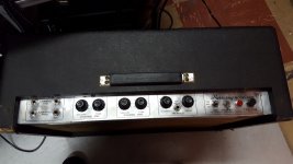
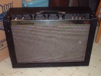
OK Amp is great! I have actually surprised myself with this one. I cannot believe how quiet it is for an old tube amp. there is no audible hum at all after the first 10 to 15 second of turning it on full. It was so quiet I actually thought it wasn't working. Got the cab re-assembled and boy she is a mighty ugly girl (no offence to girls) It looks like it has been thrown around for the last 50 years... wait a minute, it has LOL 1966 model confirmed by markings.
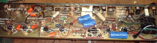
We I got it into the shop they had let some dude work on it. He put a 15amp car fuse in where a 2 amp fuse was called for. There was a meltdown of the fuse socket causing it to short mains to the chassis. He had also jury rigged a light in that was also shorted. 3 tubes were 1 DOA other 2 red plating severely. I found 3 exploded resistors and about 5 or 6 capacitors were blown completely apart or just cracked open. Amazing that the boys didn't electrocute themselves. It also had a factory non-polarized 2 prong plug. OH YEAH it had a failed death cap on the switch.. mercy.
I will attach a few pics for anyone interested.
This is officially the worse piece of crap i've ever worked on. I am now hooked on the vintage stuff and can't wait for my next hoorah.
FYI - This amp as is now sounds far better than both my Fender Princeton chorus (solid state) and my fender ultimate reverb. Both are more noisy. This little 12 watt tube job is clean and louder than the princeton chorus amp rated at 40 watts. Just an observation.
Around $175 in parts all together but i do have some spare stuff left over.
Replaced all capacitors except 4 of the ceramic disk.
Replaced most of the resistors but not all.
Replaced the multi cap can.. was most costly single part at $46 shipped.
Kept the original coils. Kept the 5Y3GT (it had been replaced at some point)
Kept the tremolo 6AU6 tube (It had also been replaced at some point)
Replaced both 12AX7 pre amp tubes with the JJ brand.. (Guy didn't want the more expensive ones)
Replaced both 6BQ5 with a matched pair from JJ (EL84) (Same as above for cost reasons)
20w 20 ohm ceramic wire-wound chassis mount resistor (to bring voltage under control)
flux and retouched every solder joint.
Cleaned and kept all the original pots. ( they seem better quality than any i have on hand)
Replaced cord with 3 prong grounded.
Replaced fuse holder and power indicator light.
Kept original jacks and switches. Cleaned guitar jacks with a bit of sand paper at the contact points.
I think that's about it.. LOL
Been to school on this one. It was worth it for the experience. thanks again for all your help.
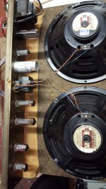
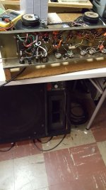
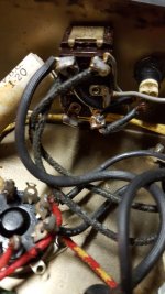
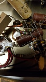
Here are 10 pics of various stages.
Attachments
-
 restore218.jpg537.2 KB · Views: 73
 -
 restore219.jpg467.8 KB · Views: 57
 -
 restore220.jpg491.9 KB · Views: 57
 -
 restore221.jpg542.2 KB · Views: 65
 -
 restore223.jpg684.7 KB · Views: 61
 -
 restore191.jpg627.1 KB · Views: 71
 -
 restore177.jpg661 KB · Views: 70
 -
 restore175.jpg587.9 KB · Views: 86
 -
 restore165.jpg606.4 KB · Views: 73
 -
 restore164.jpg597.7 KB · Views: 74

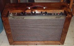
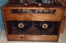
I have a 1967. I couldn't stick with the original cab since it was that near-cardboard stuff and such a big amp needs more stamina for my comfort. I saw a video on a 1965 or so and it was plywood.
Mine:
Mine:
Attachments
Nice work jjman.. I saw yours when doing my research. If the one i worked on had been my own i would have done some more things. Had to limit due to my customers budget restraints. You did some very nice work. I am happy for any level of success since this was my first vintage rebuild and i was concerned with safety and quality vs. costs. I may build some clones in the near future but i want to do an old basic build for myself... got the bug i guess. Really enjoyed the learning experience.
customer was very happy and paid more than i had asked for. (Brought me up to a whole .50 cents an hour or there about) The cost of education in my world.
Motto: Just do it.... figure it out.
customer was very happy and paid more than i had asked for. (Brought me up to a whole .50 cents an hour or there about) The cost of education in my world.
Motto: Just do it.... figure it out.
Last edited:
- Status
- Not open for further replies.
- Home
- Live Sound
- Instruments and Amps
- 1966 Harmony H415 rework - bias too high