i thought here is the best place to ask.
im making this circuit
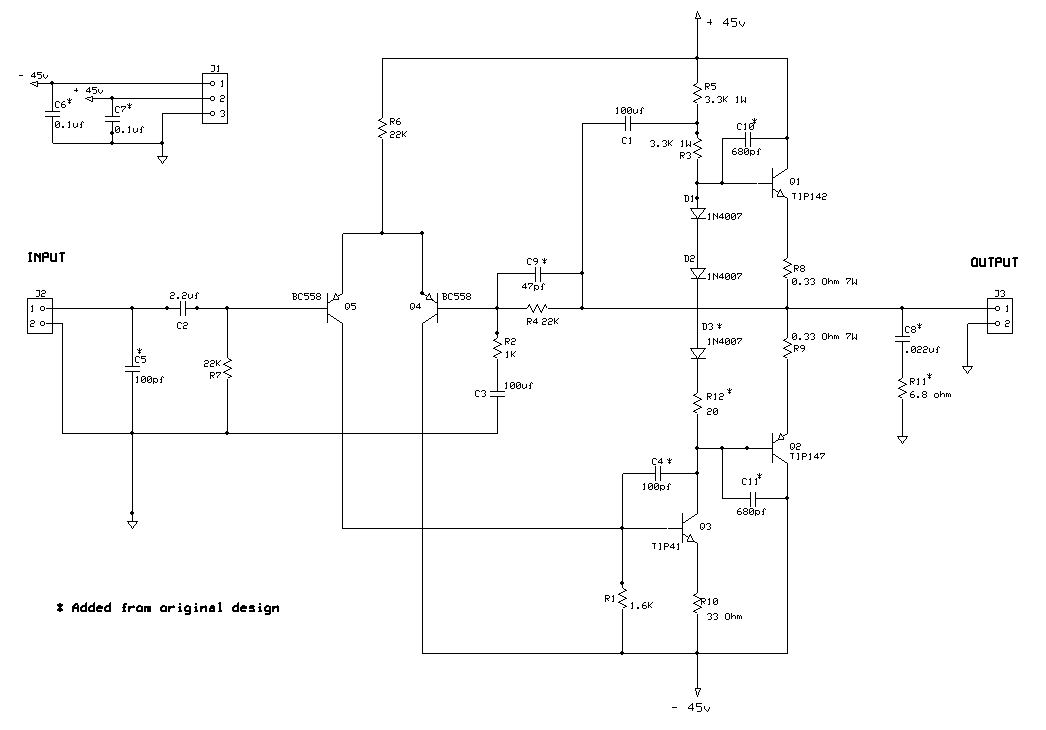
do i need heat-sink for TIP41 too? or just for two output TIP(142+147)s ?
and i cannot find 7w resistors, is it ok to use 10w instead?
thanks in advance
im making this circuit
do i need heat-sink for TIP41 too? or just for two output TIP(142+147)s ?
and i cannot find 7w resistors, is it ok to use 10w instead?
thanks in advance
Small heatsink for TIP41 might be a good idea - I think its OK at idle, but might work harder under load.
First I'd select transistors that can handle more than 30V for the differential pair! That TIP41 needs to be a TIP41C also to handle the voltage.
The feedback resistor R4 should ideally have a separate path from the bootstrap cap C1, you don't want the non-linear bootstrap cap currents imposing any voltages (due to pcb trace resistance and inductance) on your feedback sampling point - the circuit diagram ought to reflect that fact really - feedback sampling should drawn be from top of C8.
10W resistor is perfectly OK - it needs enough power handling, excess is not an issue. I suspect 7W is already rounded up from what was designed for anyway.
[ I've no idea if the bias will be good, and there's no way to adjust the bias ]
Last edited:
This is a very basic amplifier.
In principle it woks, I´d use +/-40V rails for better vreliability and load it only with 8 ohm speakers, never 4 ohm.
Expect some 70/80W RMS into 8 ohm, 150W is fantasy.
Bias diodes should be epoxied to heat sink.
And be careful with wiring and speaker connectors, it has NO protection at all.
In principle it woks, I´d use +/-40V rails for better vreliability and load it only with 8 ohm speakers, never 4 ohm.
Expect some 70/80W RMS into 8 ohm, 150W is fantasy.
Bias diodes should be epoxied to heat sink.
And be careful with wiring and speaker connectors, it has NO protection at all.
As said, TIP142/147 are not suited to more than 40V rails. Maximum voltage ratings only refer to voltage, not the high current that could be associated with it when driving speakers or other loads. However, even 5W resistors will be OK for R8,9 if they are spaced above the PCB by a few mm to allow some airflow.
I designed a TIP147/142 Darlington amplifier.
It was good for 100 watts into 8 ohms.
I went for a classic Vbe multiplier with VAS and constant current source.
It was good for 100 watts into 8 ohms.
I went for a classic Vbe multiplier with VAS and constant current source.
Would using a transistor with a higher voltage for Q4 be wise, it looks to have 90 volts across it. The datasheet suggests a lot less?
regards john
regards john
Would using a transistor with a higher voltage for Q4 be wise, it looks to have 90 volts across it. The datasheet suggests a lot less?
regards john
any suggestion on Q4, john?
this is the original pcb design i found on jspayne.
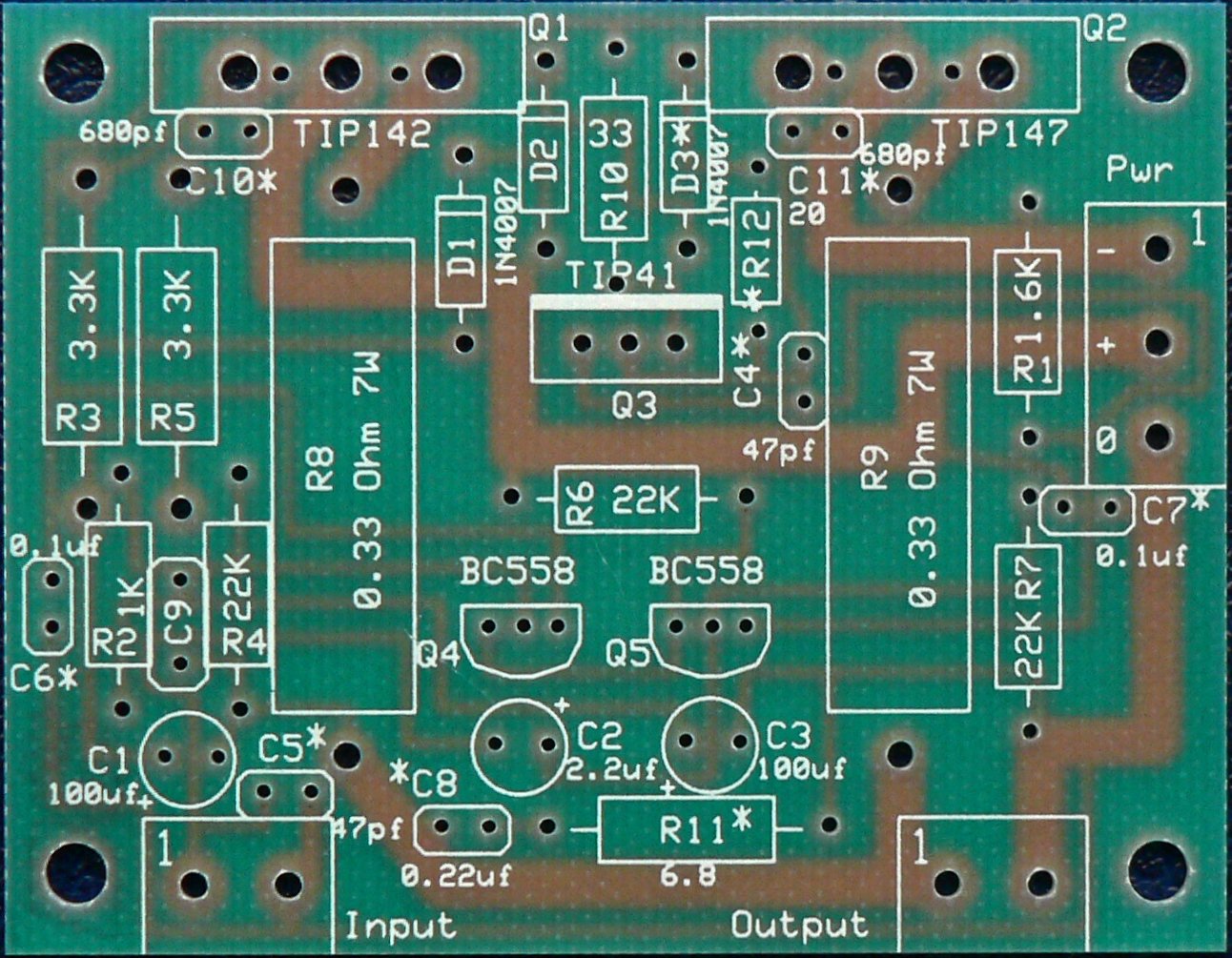
so beside puttin TIP41C on the heatsink, should i do anythind else?
i want this circuit to work constantly..
so beside puttin TIP41C on the heatsink, should i do anythind else?
i want this circuit to work constantly..
This is a very simplistic circuit, class B perhaps? Class AB bias will have bias issues due to TIP142/147 is Darlington pair. The thermal coefficient of Darlington is the product of the two Vbe junctions, where the thermal coefficient of the diodes are summed. This may lead to bias tracking issues. Really need a Darlington Vbe multiplier circuit to properly compensate, but that may be an issue with the PCB. I would say 80W average is optimistic for these devices. Also, there are fakes out there, watch out for those.

Don't forget those BC558's will blow up, some PNP's with much higher voltage rating like 2SA992 is needed. (And check pinouts, they differ between transistors).
Would using a transistor with a higher voltage for Q4 be wise, it looks to have 90 volts across it. The datasheet suggests a lot less?
regards john
Q4 will only have 45-ish volts on it. Half the supply plus the common mode input voltage - the emitters stay near ground. Even if the LTP pair did break down it would not blow up with 22k ohms limiting the current. It just wouldn’t work right, and hard to diagnose because voltage readings wouldn’t make sense. A 60 or 80 volt part would be a good idea even if 50 would technically work.
The OP could also go in the Pass Labs section and look for the AB100
It uses the same TIP142, 147
Mr Pass also generously provided the Gerber files and schematic.
BR
Eric
It uses the same TIP142, 147
Mr Pass also generously provided the Gerber files and schematic.
BR
Eric
There may be local supply problems with 2SA992 but there are also reasonable Multicomp versions of 2N5401 that should be OK with the PCB shown. 'Funny that anyone would specify the low voltage BC range of transistors in a 100W amplifier! I guess the 100W is really just nonsense. You may stretch the amplifier to 80W with an ideal power supply and heatsinking but will the average DIY do that? No, they'll be quite happy with much less power and never know the difference 😉
For Q4/Q5 BC556 works perfect (what I use as normal there) , BC557/BC560 work fine but do not exceed 45V rails.
You can use 2N5401 but Hfe is lower and you can have slightly more offset.
If it´s Saturday night and you have nothing else available in your parts box, MPSA92 can also be used, but the price paid for high voltage specs (think 300V or so) is paid for with low Hfe and relatively higher offset.
Not a fan of Japanese transistors but certainly there are many equivalents.
IN ALL CASES CHECK PINOUT.
Looking at the project page you are following (150 Watt Power Amplifier Circuit Board)
1) the original project to follow is the top one, but R3/R5 must be 3k3 each; 33k is a misprint, somebody ate the decimal point .
2) avoid the added "stability caps" , 680pF C10 and C11 , they are too large, will kill slew rate so much that amp will become sibilant and hissy with speech, go figure.
Added 47pF C9 maybe a curse or a blessing, try with/without.
3) R2 1K is fine and amp sensitivity will be more "normal" , around 1V RMS, same as a ton other amps.
4) Zobel network C8 R11 is good, it´s actually needed.
Anyone using the D2083/B1383 Sanken darlingtons? High hfe at 25 amps and pretty good 100ms SOA. I was using them for upper rail modulators in class H - was wondering if anyone has used them as an upgrade for TIP142/7 in regular class AB service. One of their weaknesses is the 10 amp current capability, with beta drooping below 500 at that 10 amps. A 25 amp transistor would do better in the THD department.
Member
Joined 2009
Paid Member
I have used the Sanken 2390 and 1560 Darlingtons
https://www.diyaudio.com/forums/sol...odified-pioneer-ht-amplifier.html#post4199133
https://www.diyaudio.com/forums/sol...odified-pioneer-ht-amplifier.html#post4199133
- Status
- Not open for further replies.
- Home
- Amplifiers
- Solid State
- 150 watt PowerAmp using TIP142+TIP147