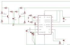
this is the test circuit that Im making
-SG3524
-trying current pulse limit (refered on other thread, from Bob Blick circuit)
-trafos are 2X EI33 from AT PSU (inductance measured for test)
each:
PRI= 7+7 turns
SEC = 20+20 turns
40KHz
regulated at +-44V
Is it aparently correct?
thanks!!
-SG3524
-trying current pulse limit (refered on other thread, from Bob Blick circuit)
-trafos are 2X EI33 from AT PSU (inductance measured for test)
each:
PRI= 7+7 turns
SEC = 20+20 turns
40KHz
regulated at +-44V
Is it aparently correct?
thanks!!
Attachments
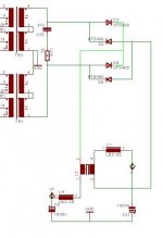
Swap the halves of the secondaries on the transformers so if there's an unbalanced load, it would not make an asymmetrical load on the transformers and require them to be derated. (In other words, make each side of the rectifier connect to a secondary on each transformer.)
Consider what each transformer would see as load if one of the outputs is loaded more than the other. It would become asymmetrical and cause problems.eltonseemann said:sorry about draw
secondaries of each single trafo is conected, im draw this wrong
each leg of each full-wave rectifier is on one extreme of series secondarie
Connect one transformer with a center tap and split the other transformer so each secondary is in series with each end of the other transformer.
OK
I understand now. Thanks, I will change this
My tests are not good, voltage rises on load. Go to +-26V at 1A simetrical.
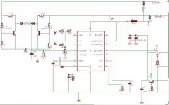
I change CT to 10nF for more deadtime on sg3524
Fosc= 33.3KHz
I understand now. Thanks, I will change this
My tests are not good, voltage rises on load. Go to +-26V at 1A simetrical.
I change CT to 10nF for more deadtime on sg3524
Fosc= 33.3KHz


I route new secondarie on same board but results are the same. 
load will be audio amplifiers (symetric)
load will be audio amplifiers (symetric)
PCB broke track
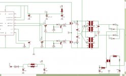
This morning I did find an stupid error on pcb. One colector at sg3524 are not at 12V (broke track at pin 12). The converter was playing on only one leg . capable of 50W load
Now results are more satisfactory
Im working on current limit, this work well.
I impement an idea found on other thead, thanks Eva, rectifying primary legs to supply driver circuit
This morning I did find an stupid error on pcb. One colector at sg3524 are not at 12V (broke track at pin 12). The converter was playing on only one leg
. capable of 50W loadNow results are more satisfactory
Im working on current limit, this work well.
I impement an idea found on other thead, thanks Eva, rectifying primary legs to supply driver circuit
Even audio amps are not symmetrical loads. Even a transient asymmetry will require the transformer to be derated.eltonseemann said:I route new secondarie on same board but results are the same.
load will be audio amplifiers (symetric)
Re: PCB broke track
Your MOSFETs will run cooler due to the reduced Rds-on at higher Vgs, however, be careful to not exceed 20V at the gates under any circumstances.
eltonseemann said:
I impement an idea found on other thead, thanks Eva, rectifying primary legs to supply driver circuit
Your MOSFETs will run cooler due to the reduced Rds-on at higher Vgs, however, be careful to not exceed 20V at the gates under any circumstances.
Re: Re: PCB broke track
20v gate drive is too high for most MOSFETs. Most gate drive circuits work with voltages of 12v or so. However, driving the gates slightly negative when turning off can increase efficiency. (It counteracts stray capacitance that couples the rising drain voltage which slows turn off of the MOSFETs.)Eva said:
Your MOSFETs will run cooler due to the reduced Rds-on at higher Vgs, however, be careful to not exceed 20V at the gates under any circumstances.
- Status
- Not open for further replies.
- Home
- Amplifiers
- Power Supplies
- 12V CT push-pull series secondaries