The other half of the Akai conversion I'm doing(now that I have the Ef86 pre mostly sorted(thanks) is based on a 12ax7
It also uses a shure M67 input transformer.
The problem I'm seeing is that it will overdrive itself before it overdrives the inputs of my UAD apollo 11
So whilst I can record a clean signal, it is not very loud. For a regular not too loud vocal this happens between 4-5 on VR1 At this point I am only halfway to distorting on my Apollo 11 unit. It would be nice if I could get a louder clean signal at the Apollo 11 unit, so I can meter there and not the U meter on the pre
If I turn up the pre louder it just starts distortion and I get a distorted flattened signal reminiscent of Skeletor
Coincidentally or not, this distortion happens when the VU meter of the preamp bounces into the red. However this VU meter is actually powered by the output transformer and power amp.
Originally the schematic had a connection at the preamp output which grounded the input of the power amp when a patch chord was plugged into the preamp out., however this also turns off the VU meter which frankly is no fun!, also i jumpered this on mine and it made no difference ot the distortion issue, except to turn off the fun VU meter.
Any ideas what's overdriving here? Is this another output impedance mismatch ?
v1 plate is 93V
cathode is .923
v2 plate is 126
cathode is 1.19
Attachments
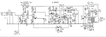
When the VU meter at the output is in the red, the 6BQ5 power stage is overdriven into distortion and / or clipping.
That distorted signal is fed back to the AX7 cathode, which unfortunately is also your pre out.
If you do not use the power stage and don't need the VU meter anyway, you can simply pull the 6BQ5.
If you want to still use the power output once in a while you could install a switch to turn off the heater of the 6BQ5. Same effect ...
12AX7 with 250k plate resistor can "drive" not smaller than 500k load.
Modern pre amplifiers typically have 10k input resistance.
The output of 12AX7 must be buffered.
And the output must not be taken at the plate of 2nd 12AX7 halve, because it is in the GNFB loop and therefore the signal there is distorted.
The output is only possible to be taken at the plate of the first 12AX7, but needs a cathode follower as a buffer.
Last edited:
Thanks a lot for the replies. I appreciate any and all input
- Well I have tried sending the 6BQ5 input to ground and I have tried removing the 6BQ5 and neither makes any difference in the preamp output. It still clips at the same level so if you turn it up you get a signal of the same volume but increasingly distored. THis is with the power amp disabled.
- The preamp out signal is taken from the cathode of the second stage so it's not coming from the plate of the second stage.
However I think your thoughts regarding impedance might be close to the mark, I am woefully uneducated in electronics though.
What is the AC-level at the cathode of V2b when the clipping begin ?It still clips at the same level...
According to simulation, the clipping take place when the AC-voltage at the grid of 12AX7 exceeds 2 Vrms.
Then the AC-voltage at the output (cathode) is 1 Vrms.
This not very good circuit as a pre amplifier.
Thanks for your response. Do you have any suggestions on how to improve it? I will admit I'm not entirely sure how to measure this but I set my meter to AC hooked up a ground and then put the hot on the cathide and sang into it watching the wave form. it seems to measure between .2-.3VAC when it's clipping
Last edited: