Hello
This is my first try with the tubes so please forgive me if my questions are stupid.
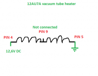
I am going to use 12AU7 in the input stage of hybrid amplifier and I am going to use DC for the heater (prefered 12.6V). The supply will be stabilised at approx 12.4V.
Can I leave pin 9 not connected to anything ?
THX
Peter
This is my first try with the tubes so please forgive me if my questions are stupid.
I am going to use 12AU7 in the input stage of hybrid amplifier and I am going to use DC for the heater (prefered 12.6V). The supply will be stabilised at approx 12.4V.
Can I leave pin 9 not connected to anything ?
THX
Peter
Attachments
Yes it's ok..
It's there in case you have a 6.3 volt heater power supply instead, so you connect 6.3 volt between pin 9 and pin4+5 combined.
Not sure about connecting pin 5 to ground. Depending on your schematic, it may need to be elevated.
It's there in case you have a 6.3 volt heater power supply instead, so you connect 6.3 volt between pin 9 and pin4+5 combined.
Not sure about connecting pin 5 to ground. Depending on your schematic, it may need to be elevated.
Thanks
And I have another few questions.
1. Would be recommended to put NTC thermistor in series with heater as a soft start for heating ?
2. Heating time is approx 11s, what is happening with bias current (cathode current), is it slowly rising up while heater is reaching its nominal temperature ?
Thanks
Peter
Thanks
And I have another few questions.
1. Would be recommended to put NTC thermistor in series with heater as a soft start for heating ?
2. Heating time is approx 11s, what is happening with bias current (cathode current), is it slowly rising up while heater is reaching its nominal temperature ?
Thanks
Peter
Have you seen these?
CL Series Inrush Current Limiters - Amphenol Advanced Sensors | DigiKey
Thanks
2. Heating time is approx 11s, what is happening with bias current (cathode current), is it slowly rising up while heater is reaching its nominal temperature
If there isn't a soft start circuit or B+ is unregulated the cathode sees it's full voltage immediately. Regulators provide a slow start up, it's faster than the heat up time, but it's still slow enough to watch on your DMM.
Whether or not you need a soft start will depend on your circuit, and is beyond my ability to answer. I'm sure someone here will chime in.
No need for a soft start, unless your 12V supply can't cope with the initial current surge. This is a common problem found by people using DC heaters; their regulator goes into shutdown mode due to overcurrent protection.
Cathode current will rise as the cathode heats up. The rest of your circuit needs to cope with this.
Cathode current will rise as the cathode heats up. The rest of your circuit needs to cope with this.
No need for a soft start, unless your 12V supply can't cope with the initial current surge. This is a common problem found by people using DC heaters; their regulator goes into shutdown mode due to overcurrent protection.
Cathode current will rise as the cathode heats up. The rest of your circuit needs to cope with this.
Hi Df96,
Could you give me an example in how to make sure the circuit can cope with those inrush-currents, for example, I am using a transformer with determined specs (200V/1A and 16V/1A, but I don't know about its 'resistance') but beefed up the caps, both in B+ and heater circuits. And I suspect an inrush problem, could the caps enlarge the inrush? I suspect so...
Thanx in advance, Stef.
Last edited:
I was speaking of the initial current surge into a cold valve heater, not the inrush current into a discharged reservoir cap. Big caps can increase inrush, as can big transformers, but this is a quite separate issue.
The surge into a valve heater can be 3 or 4 times the normal 'hot' current, so if someone designs a DC supply using a normal regulator and does not take account of this the supply may never come on properly. You take account of it by ensuring that your supply can deliver the initial current for at least a few seconds. I don't use DC heaters myself, so I am only going by the cries of newbies on this forum.
The surge into a valve heater can be 3 or 4 times the normal 'hot' current, so if someone designs a DC supply using a normal regulator and does not take account of this the supply may never come on properly. You take account of it by ensuring that your supply can deliver the initial current for at least a few seconds. I don't use DC heaters myself, so I am only going by the cries of newbies on this forum.
Thank you for the explanation, so we learn as we move along, those newbees must be a terrible pain in the ****, I'm sure! Stumbling and fumbling in darkness and depending on knowledge already gained....  This is the first time I read that cold valve heaters in DC operation have a current surge, I wasn't aware of that. I would like to learn how to counter that and I will try to find some info on this!
Cheers, Stef.
This is the first time I read that cold valve heaters in DC operation have a current surge, I wasn't aware of that. I would like to learn how to counter that and I will try to find some info on this!Cheers, Stef.
We were all newbies once!
All valve heaters fed from a voltage supply, whether AC or DC, have a current surge as the cold heater has a much lower resistance than a hot heater. An AC supply and some simple DC supplies usually limit this a bit by their source impedance. A regulated DC supply has, by design, a very low impedance so this maximises the surge. One option is to make a supply for a slightly higher voltage and add a dropper resistor - wastes power but if you were worried about efficiency you would not be using valves at all. Alternatively just make sure the supply can cope.
All valve heaters fed from a voltage supply, whether AC or DC, have a current surge as the cold heater has a much lower resistance than a hot heater. An AC supply and some simple DC supplies usually limit this a bit by their source impedance. A regulated DC supply has, by design, a very low impedance so this maximises the surge. One option is to make a supply for a slightly higher voltage and add a dropper resistor - wastes power but if you were worried about efficiency you would not be using valves at all. Alternatively just make sure the supply can cope.
No need to delay HT/B+ voltage with normal valves - this is only needed for some very high power valves, such as those used in transmitters and serious PA. Elsewhere, the surges caused by such delay can create their own problems.
- Status
- Not open for further replies.
- Home
- Amplifiers
- Tubes / Valves
- 12AU7 - 12.6V DC heater wiring - noob