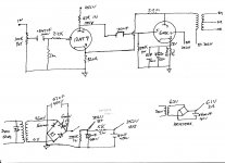
I was given a 12at7 tube so I built this good sounding amplifier, I was wondering can anybody see problems with the schematic ?? I went to different websites for the right calculations and was hoping I having made major problems? it is up and running and sounds good no hum I playing youtube music and the amp has great low end and no overpowering high end overall a great sounding amp.
Attachments
Damping factor in amps employing full pentode mode "finals", without NFB of some kind, will be poor. Are the speakers mated to the amp somewhat bass shy? "Loose" bass is to be expected, when an inadequate damping factor is present.
Damping factor in amps employing full pentode mode "finals", without NFB of some kind, will be poor. Are the speakers mated to the amp somewhat bass shy? "Loose" bass is to be expected, when an inadequate damping factor is present.
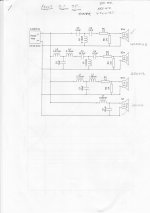
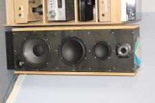
This is my own design 4 way speaker system that I have done for front 5.1 surround sound and for my tube amplifiers xover points are 350hz 550hz and 4000hz it has enough lower end I don't need subwoofer. through these it sounds pretty great the bass thumps it out very tight not loose and I have global feedback circuit which seems to work well in the circuit, as I said I'm not expert but it does sound to my ears
Speaker system : 10" low woofer
8" mid woofer
5" midrange
2" Tweeter
Attachments
You will indeed want some feedback or to triode wire that output tube. As it is, this would be well suited as a guitar amp.
I also don't agree with the way the 12AT7 is arranged. The coupling cap isn't necessary and the grid stopper would work just as well if it was a lower value. I also no longer bother with the 1M "backup" resistor that's between the pot wiper and ground.
I also don't agree with the way the 12AT7 is arranged. The coupling cap isn't necessary and the grid stopper would work just as well if it was a lower value. I also no longer bother with the 1M "backup" resistor that's between the pot wiper and ground.
Last edited:
Damping factor in amps employing full pentode mode "finals", without NFB of some kind, will be poor. Are the speakers mated to the amp somewhat bass shy? "Loose" bass is to be expected, when an inadequate damping factor is present.
this is the speakers I have matched to the tube amp? is that not right either? be interested in your thoughts thanks
Attachments
Two things:
1) Doesn't the 2.2M resistor connected from the plate of the 6L6 to the cathode of the 12AT7 provide a feedback loop? That should help damping factor of the output stage. Perhaps that 2.2M resistor value could be reduced to provide more negative feedback, and it might need to have a blocking cap in series to block DC current from flowing between the 6L6 plate and 12AT7 cathode. Maybe 1M and 0.22uF?
2) The 1M 'backup resistor' from input pot wiper to ground keeps a resistive load on the 12AT7 grid if/when the pot fails. It does no harm, and it could help, so what's wrong with it?
You could move the input blocking cap to before the volume pot instead of after it. That would keep any DC leakage off the pot. Minor quibble, tho'.
Just my $0.02, fwiw...
The 2M2 resistor provides some feedback.
Positive feedback.
Connect it (lower value) to the anode of the driver and it is known as 'Schade' (negative) feedback.
Many moons ago I had a PP amp where I used high ohm resistors from the anode of the output valve to the kathodes of the driver of the oposite phase.
Positive feedback.
Connect it (lower value) to the anode of the driver and it is known as 'Schade' (negative) feedback.
Many moons ago I had a PP amp where I used high ohm resistors from the anode of the output valve to the kathodes of the driver of the oposite phase.
That output-plate to driver-cathode resistor shouldn't make positive feedback, if between two stages. It should still reduce gain (along with reducing distortion and rp of the output stage). You can cross-couple that feedback too.
What people here call 'Schade' feedback is actually plate-grid local feedback. It gets discussed here a lot. But that won't work very well with a triode driver stage. You'd want a pentode driver stage if you're using plate-grid feedback around the (pentode) output stage.
What people here call 'Schade' feedback is actually plate-grid local feedback. It gets discussed here a lot. But that won't work very well with a triode driver stage. You'd want a pentode driver stage if you're using plate-grid feedback around the (pentode) output stage.
I was given a 12at7 tube so I built this good sounding amplifier, I was wondering can anybody see problems with the schematic ?? I went to different websites for the right calculations and was hoping I having made major problems? it is up and running and sounds good no hum I playing youtube music and the amp has great low end and no overpowering high end overall a great sounding amp.
Then there are no problems 🙂
The only thing I see here is that the lNFB loop isn't doing much of anything. A voltage divider with a series 2.2M resistor and a parallel 820R resistor has a voltage gain of:
820/(2.2E6 + 820)= 3.73E-4 (-68.6dbv)
One volt in gives 373uV out. It's basically doing nothing. If you want lNFB, then you'll need a smaller series resistor, and DC isolate it with a capacitor. Since the amp sounds good as is, then there's no need to change it, at least not until you've spent some time with it to see if you later notice any improvements you might need.
> One volt in gives 373uV out.
Or another way: 2.2Meg:820 is 2700:1. If the forward amp has infinite gain, that's what the gain will be with NFB.
The gain of 12AT7 is less than 40; 6L6 with nominal load usually near 10. So forward gain is 400.
Forward gain 400, NFB 2,700.... there is nearly no NFB happening at nominal load.
6L6 gain will increase with load. Speakers have bass impedance bump. If the "8 Ohm" speaker rises to 53 Ohms, the NFB just barely controls that bump. Speakers often get to 50 Ohms in the bass bump. We have just a trace of damping on just some speakers.
A smaller "2.2Meg" will damp more, but also tend to disrupt 12AT7 bias. A coupling cap looks like an answer but if the NFB is not-tiny it leads to a response *rise* at subsonic and possible flubby sound.
I think the amp is OK as it stands. It is not how I would do it, and I would not bet on smooth bass response from "all" hi-fi speakers. BUT MDamp says he is happy, so we should all be happy.
- Status
- Not open for further replies.
- Home
- Amplifiers
- Tubes / Valves
- 12AT7 6L6GC Tube DIY Amplifier