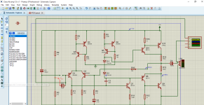
There should be a connection from R6 to ground.
Also the input is not correct.
Also the input is not correct.

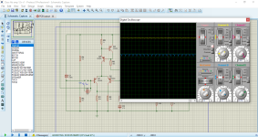
now i am getting output signal but that signal is still not stable will show the screen shot of the input signal .. thanks for your great copration

Attachments
Last edited:
Q 1 is connected with in put signal through capacitor value of 10uf. I want build this circuit but before going further into this I would like to get some experts advice on this circuit
@Hamid711
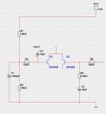
Here is a part of schematic with changes I should make.
1. The input should work this way. See image. Observe the polarity of C2.
2. The gain is too much. So change resistor R9 to 6.8k. This will be a better level of gain.
For only 12V there is not much gain needed.
Here is a part of schematic with changes I should make.
1. The input should work this way. See image. Observe the polarity of C2.
2. The gain is too much. So change resistor R9 to 6.8k. This will be a better level of gain.
For only 12V there is not much gain needed.
Attachments
@Hamid711
I do not know how to measure distortion with your software.
But output power.
1. increase the input signal until the amp starts to clip.
2. measure the output signal
3. Watt = Vout*Vout/loudspeaker-ohm
R7 is 18k. Make R6 also 18k. (180k is way to much)
Remove R2. It is better without it.
Make R1 = 3.3k
Make C2 = 10uF
If you do this you have a good amplifier 🙂
Then Q1 is unbiased.Q 1 is connected with in put signal through capacitor value of 10uf. I want build this circuit but before going further into this I would like to get some experts advice on this circuit
That schematic is wrong and/or has errors of very iffy choices, where did you get it from?
Looks amateurish to say it mildly.
To boot it might have filled a need in the 1960s or so, not much interest today in a relatively complex 12V discrete amp capable of only a couple Watts.
Any car radio class chipamp fills that need, for peanuts.
the schematics has many errors and with the help of
i know that the modern chip amps are good and very cheap as well . but i want to build a transister amp that can be run on a single supply like 12 to 24 volt single rails and provide 3 to 10 watt of an output power if you have any good schematics of a transister amp of single supply please share with me will try that
lineup
i have mange to solve those problems .i know that the modern chip amps are good and very cheap as well . but i want to build a transister amp that can be run on a single supply like 12 to 24 volt single rails and provide 3 to 10 watt of an output power if you have any good schematics of a transister amp of single supply please share with me will try that
- Home
- Amplifiers
- Solid State
- 12 volt Class Ab amplifier has no output signal on the speaker side