I replaced a 10K Ohm plate resistor in
a common cathode stage
by a 10M45S (5K trimpot, 1K grid stopper)
10mA constant current source (CCS).
I heard a small pop/thump sound momentarily AFTER power down the amp,
didn't have that with resistor.
Out of the 5 "identical" copies of 10mA CCS that I made,
only one doesn't have this issue.
I have also tried cascoded CCS, 10M90, various trimpots
... the "pop" persists.
I wonder what would cause this "pop" ???
Would it be some kind of residual current in the CCS
(like a choke which can be fixed with a flyback diode ) ?
The 10M45S CCS does not have energy storage ?
So I tried the flyback diode .. I tried bypassing the trimpot
with 10Meg resistor .. both didn't work.
Suggestions ? Insights ? TIA
What value of Gate Stopper resistor did you use?
Solid state devices change their capacitance and effective 'frequency response' when they have large change of voltages. Parasitics cause oscillations, but only at certain voltage levels. A current source IC with multiple parts in the chip is no different.
Often, it is the impedances external to the IC that causes an oscillation or change of state (step function).
Please post a complete schematic (Amp and power supply, with voltages marked).
Otherwise, just shoot an arrow at the target . . .
(after you are blindfolded, and then rotated an unknown amount between 180 degrees and 360 degrees).
I have used the 900V version of the part on several amplifiers (just one part per plate).
I am about ready to use the 450V part now on another amp that has a much lower voltage un-loaded B+ supply.
Last edited:
Gate stopper is 1K.
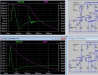
I ran two simulations to observe the power off transients.
Top figure is with CCS plate load, bottom figure is with resistor load.
Power is turned off @ 40ms.
Green (Vload) is output, speaker.
Purple is the current of CCS/resistors.
Looks like CCS is trying to keep the current going for another 140ms,
(after all it is a CCS !)
whereas the resistor load decays much faster.
Attachments
1. Look at how fast the two tubes current collapses.
When the 2nd tube current goes down, the 2nd tube cathode voltage goes down, and the current source begins to pump current into the grid protection diode of the 2nd tube, and through that diode to the self bias network.
The B+ of the current source may have a different collapse rate, than the B+ for the 2nd tube, Take a look at those RC collapse rates.
2. You forgot to draw the 1k Gate Stopper resistor into your schematic.
You need that, or a newbie will copy that stage.
(and they will wonder where the oscillations come from).
3. With solid state devices, the oscillation or transient can happen because the voltage across the IC varies, and the ft varies according to voltage and current. For a MOSFET device I do not know what they call the MOSFET equivilant of the "ft of a bipolar" but a similar effect applies to MOSFETs, and so do parasitic oscillations.
And MOSFETs also have Gate Charge effects (in micro Coulombs). You have a Switch if you have a MOSFET.
Last edited:
You could try burning off some of the voltage across the CCS with a high value plate stopper. A current bench amp uses 7K on top of a relatively high mu triode. Driving the stopper with a CCS means it sees minimal audio current/voltage though it does increase significantly with frequency. With a stopper both the CCS and the tube get a benign resistive load to far above the audio band.
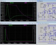
Again, power is turned off @ 40ms.
With a plate stopper, current decays quickly ...
but the initial transient shoots up to 6V !!
Bottom figure shows CCS with plate stopper.
Top figure shows CCS (without plate stopper)
with reduced C4.
Lesson learnt (for me) is: choose capacitance carefully
to provide a gracious power down.
Thank you all for your contributions.
Attachments
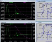
In Post # 3, you can see the current source oscillating at very high frequencies.
Look for the broad trace on the first rise of the transient. And then look for the broad trace after the second positive transient.
And, I think there may be an oscillation at the crest of the second positive transient.
It seems that the 1k gate stopper fixed that part of the problem.
I say this, especially for newbies who may have oscillation on their CCS circuits, even if the rest of their tube circuit is different.
But you have more to work on.
I think it is more a problem with the tube circuit parts and values, but in someways, the resistive plate load looks the best overall.
Notice the glitch at about 200 msec on the first screen shot of Post #6.
I wish I had a good idea of how to get rid of the transient altogether, but I do not see anything obvious.
With the 10mA current source, and DC coupling to the 2nd tube grid, I can understand why you are using a diode across the grid to cathode.
I still wonder about that diode, the current that now goes straight to and through the self bias RC of the 2nd tube, when the B+ to the 2nd tube collapses.
Since you are doing simulations, you can take the diode out of the simulation, and not destroy the 2nd tube grid, simulations allow that.
Do it to see what happens to the waveform.
Last edited:
- Home
- Amplifiers
- Tubes / Valves
- 10M45S CCS plate load ... hear a pop