I've been repairing/restoring/rehabilitating a great 30-year old pair of speakers and I have some questions stemming from my novice inexperience.
1) In the woofer part of the crossover, the schematic shows a "100uF 100V bi-polar" in parallel with the woofer. My existing crossover, spare crossover that I purchases, and in every photo that I've seen of the crossover, they use two 47uF caps instead of one 100uF cap. Why?
Why not two 50uF caps (which certainly appear to be available)? I understand that two smaller value caps might perform better than one large value cap (correct me if that understanding is wrong), but why use 47uF caps?
I will certainly re-build this cross over with some type of Metalized Polypropylene cap. But do I use two 47uF (maybe with an added higher-quality bypass cap) or two 50uF caps?
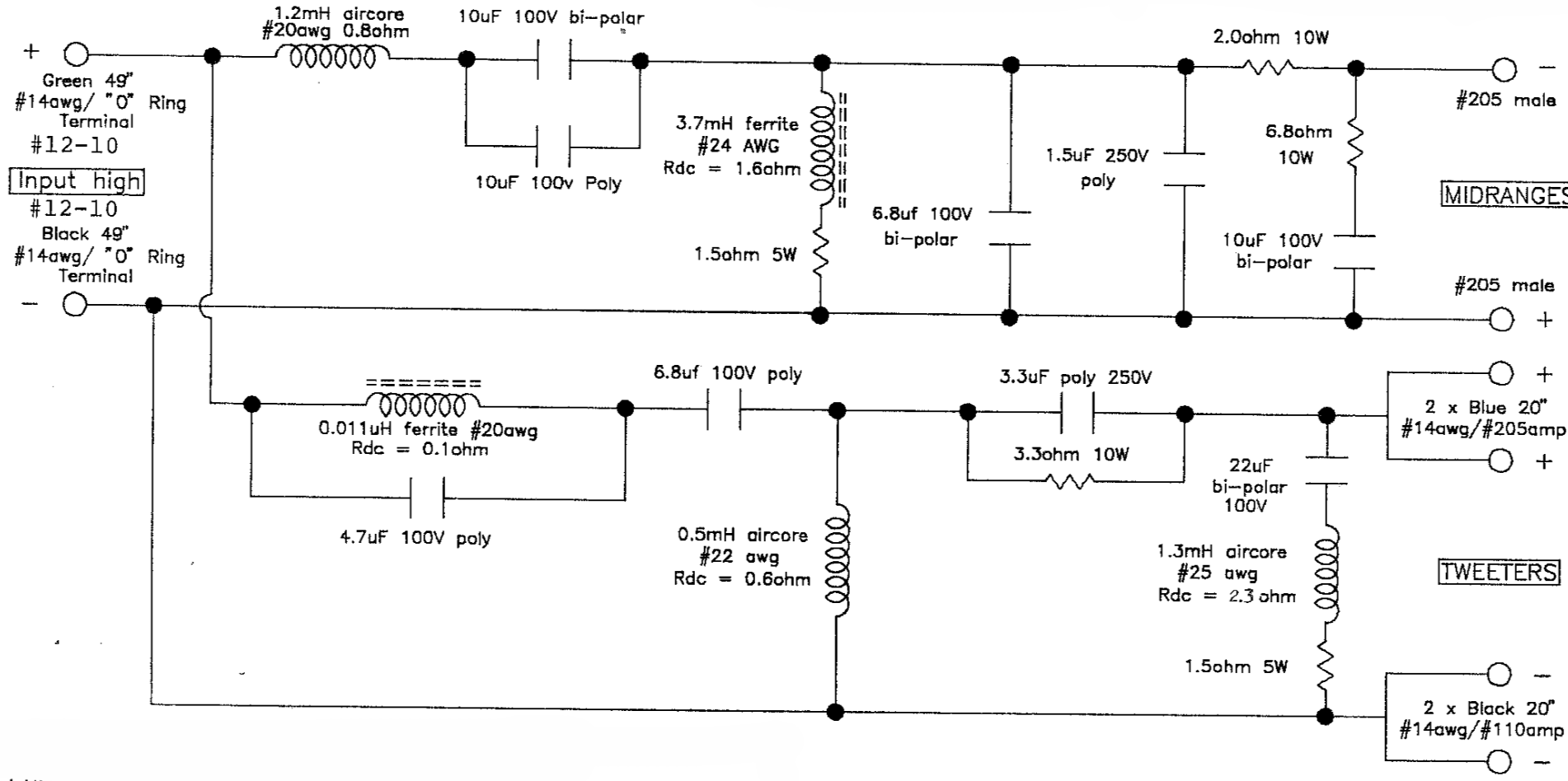
2) In the midrange section of the crossover, it has two 10uF caps in parallel wire in series with the midrange drivers. See attached snippet from the schematic:

As with the woofer circuit, I will probably replace these with Metalized Polypropylene caps. I assume I can use one 20uF poly cap rather than two 10uf poly caps without any significant difference in quality. Or will two 10uF actually be much better?
3) In the tweeter circuit there are 3 inductors. The first in series with the tweeters is a very small 0.011uH ferrite core inductor with a Rdc of 0.1 ohm (the other 2 are 0.5mH and 1.3mH inductors wired in parallel with the tweeters). Following the concept that ferrite core inductors are problematic, particularly in series with tweeters, I am considering replacing it.
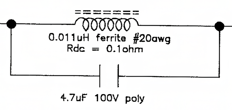
None of the speaker parts sellers (Madisound, Parts-express, Parts-connexion) have any inductor that small. Is that possibly a typo? (I will have to see if I can measure the inductor) 0.011uH = 0.000011mH = 11nH. Does a value that small make any sense to any of you? I would like to replace it with an air core (for obvious reasons) and I can find air core inductors in roughly that size (0.010 uH) on digikey.com. But the size does seem strange to me. Further, if it is correct, the Rdc of the inductor will almost certainly be different. Do I need to compensate for the different resistance in the circuit, and if so how or where would I do that? This is what the 11nH inductor looks like:
1) In the woofer part of the crossover, the schematic shows a "100uF 100V bi-polar" in parallel with the woofer. My existing crossover, spare crossover that I purchases, and in every photo that I've seen of the crossover, they use two 47uF caps instead of one 100uF cap. Why?
Why not two 50uF caps (which certainly appear to be available)? I understand that two smaller value caps might perform better than one large value cap (correct me if that understanding is wrong), but why use 47uF caps?
I will certainly re-build this cross over with some type of Metalized Polypropylene cap. But do I use two 47uF (maybe with an added higher-quality bypass cap) or two 50uF caps?
2) In the midrange section of the crossover, it has two 10uF caps in parallel wire in series with the midrange drivers. See attached snippet from the schematic:
As with the woofer circuit, I will probably replace these with Metalized Polypropylene caps. I assume I can use one 20uF poly cap rather than two 10uf poly caps without any significant difference in quality. Or will two 10uF actually be much better?
3) In the tweeter circuit there are 3 inductors. The first in series with the tweeters is a very small 0.011uH ferrite core inductor with a Rdc of 0.1 ohm (the other 2 are 0.5mH and 1.3mH inductors wired in parallel with the tweeters). Following the concept that ferrite core inductors are problematic, particularly in series with tweeters, I am considering replacing it.
None of the speaker parts sellers (Madisound, Parts-express, Parts-connexion) have any inductor that small. Is that possibly a typo? (I will have to see if I can measure the inductor) 0.011uH = 0.000011mH = 11nH. Does a value that small make any sense to any of you? I would like to replace it with an air core (for obvious reasons) and I can find air core inductors in roughly that size (0.010 uH) on digikey.com. But the size does seem strange to me. Further, if it is correct, the Rdc of the inductor will almost certainly be different. Do I need to compensate for the different resistance in the circuit, and if so how or where would I do that? This is what the 11nH inductor looks like:
Last edited:
Regarding the capacitors, manufacturers often make use of those they have in stock or of those which offer them the best value when buying in bulk.
Hence the use of two 47 uF capacitors in parallel to emulate a single 100 uF. Use two 50 uF by all means, but it is unlikely to result in an audible difference.
And you could replace the two 10 uF caps in parallel with a single 20 uF.
P.S. What loudspeaker is this?
P.P.S. There may be technical reasons for the mixture of poly and bi-polar capacitors rather than it simply being down to the greater expense of large value poly caps - and its likely the crossover experts may have an opinion on that.
Last edited:
It's a more common value.but why use 47uF caps?
https://en.wikipedia.org/wiki/E_series_of_preferred_numbers
Maybe it's used for EQ. Why not try winding it yourself..11nH. Does a value that small make any sense to any of you?
Regarding the ferrite inductor in parallel with the poly cap in the tweeter circuit, I believe the generic name for such a circuit is a 'contour network'.
As AllenB implies, its function is likely to be that of modifying the frequency response of the tweeter in some subtle manner.
I submit that substituting an air core coil of the same inductance, but of necessarily greater resistance, would alter the function of the contour network.
I response to your concern about the contour circuit being in series with the tweeter, consider that it may only be active over a limited range of frequencies while leaving the main signal to the tweeter unimpeded. AllenB, being the resident expert on crossovers, is welcome to correct me on that if necessary!
In short, my suggestion is that you leave the LC contour network exactly as it is.
Knowing that I'm only human, I thought I'd simulate it. The value is of course unusual. I would feel more comfortable measuring it than using the stated value.
I probably could. I've got a lot of 14 or 16AWG magnet wire hanging around here. Measuring something that small, however, might be beyond the capabilities of my analyzer.Maybe it's used for EQ. Why not try winding it yourself..
Yes, vituixcad won't even simulate something that small. You'd have to use an independent resonance test to get there.
Can I propose a test to set your mind at ease. Try shorting the coil (which will also short the capacitor it's connected across). If you can hear a difference then it's likely not the printed value. (The picture doesn't look it either.)
Can I propose a test to set your mind at ease. Try shorting the coil (which will also short the capacitor it's connected across). If you can hear a difference then it's likely not the printed value. (The picture doesn't look it either.)

You could rebuild the rest of the xover and try the contour circuit in and out as an experiment. If it sounds better with it, then go to the trouble of "fixing" that portion.
Is there some benefit of using two 47uF or 50uF caps instead of a 100uF cap (assuming size is not an issue)? Or perhaps even 2 caps of different sizes to reach total desired capacitance?Hence the use of two 47 uF capacitors in parallel to emulate a single 100 uF. Use two 50 uF by all means,
The only benefit to using two caps in parallel that I can think of is the tolerances might balance out between them. 'Lytic caps, even the good ones brand new, are spec'd +/- 20%. This is one of the reasons they're not very good for xovers, unless they're selected by actually measuring. If you use two in parallel, the tolerances might offset between them and you'd be closer to the target value. Buy a bunch and measure to obtain valid pairs. You will never hear the difference between 47uf and 50uf, so buy the more common value to get better value and quality, and a MUCH greater selection (2 available versus 1200 at Mouser!). You may very well get 50uf anyway, as I have found they usually measure high.
My attention is drawn to the parallel arrangement of 10 uF bi-polar cap and 10 uF poly cap in the midrange section.
What might be the benefit of this combination?
P.S. I can't help but notice that the make and model of this loudspeaker still remains a mystery!
What might be the benefit of this combination?
P.S. I can't help but notice that the make and model of this loudspeaker still remains a mystery!
LOL. I didn't want to color the discussion with potential brand prejudices.P.S. I can't help but notice that the make and model of this loudspeaker still remains a mystery!
The speakers are Mirage M-3si "bipolar" speakers. They are over 30 years old and never felt the need to replace them. Like most M-3si owners, I love them. The drivers are out for refurbishment (surrounds and ferrofluid replacement) and figure that all those electrolytic caps are past their useful life as well. So replace the caps and if I can further increase transparency, detail and space in the process -- great. They will be good for another 30 years.
For reference: https://www.stereophile.com/floorloudspeakers/1192mirage/index.html
Yes. That plus, from what I found, that multiple smaller capacitors in parallel can offer significant advantages in terms of ESR, high-frequency performance, ripple current handling, and heat dissipation (which might not really be an issue). How much of a difference this will actually make in practice might be hard to see or predict.The only benefit to using two caps in parallel that I can think of is the tolerances might balance out between them.
The reduction in ESR (small to begin with) obtained by using parallel 47 uF caps in the woofer circuit instead of a single 100 uF cap is unlikely to have any significant audible effect. And, of course, in the woofer circuit, any advantage in HF performance shouldn't enter the equation.
EDIT: Actually, the woofer filter is shown correctly in this full circuit diagram:

EDIT: Actually, the woofer filter is shown correctly in this full circuit diagram:
Regarding the 11 nH ferrite inductor in the tweeter circuit, I read that, compared to an iron core inductor, a ferrite core inductor has lower losses at high frequencies and a higher Q factor.
I also read that its function is to protect the tweeter from extraneous HF out of the range of human hearing. As its effect is supersonic an air coil isn't necessary. In particular, the ferrite inductor could be necessary if the titanium dome tweeter exhibits a nasty HF resonant peak.
That's just what I read, the crossover experts may confirm or deny. Perhaps Mirage knew what they were doing.
https://audiokarma.org/forums/index...-why-and-should-i-upgrade-to-air-core.991368/
EDIT: I notice you have posted a photo of the crossover board on the AudioCircle site where you have enquired about the 11 nH ferrite inductor:
Last edited:
I'd question that post on all points. The only value that appears to make sense is 11uH, as it shows the kind of management you'd expect for cone breakup.That's just what I read,
Bo Dacious, I'd advise care when renewing this inductor. It's narrowband effect means that compared to other components you'll want to tune it, ie adjust it to the needed frequency, otherwise it will be ineffective.
I'd question that post on all points.
However you seem to be agreeing with the post regarding the ferrite inductor being used to control a resonant peak of the tweeter's metal dome that lies at an ultrasonic frequency (>20 kHz on your graph) - provided of course that the correct value of the inductor is 11 uH and not 11 nH.
Have I interpreted your above simulation correctly?
However you seem to be agreeing with the post regarding the ferrite inductor being used to control a resonant peak of the tweeter's metal dome
Not at all. This is what was written...
This implies a wideband effect like the output inductor which you'll find used at an amplifier's output (where it should be located). This is like chalk and cheese comparing to a notch filter. It would be ineffective against such a resonant peak.Its there to protect the tweeter from extraneous HF out of the range of human hearing and to protect amplifiers by providing a load. Some amps go crazy when pushed if they don't have a very high frequency load.
Here is my vituixcad simulation, I'd welcome a second opinion.provided of course that the correct value of the inductor is 11 uH and not 11 nH.
Attachments
So you've been doing some reading but maybe not enough thinking. ESR means nothing if there are resistors in series with the caps! High freq means nothing in the woofer circuit. And if you have ripple current there, you're screwed anyway.Yes. That plus, from what I found, that multiple smaller capacitors in parallel can offer significant advantages in terms of ESR, high-frequency performance, ripple current handling, and heat dissipation (which might not really be an issue). How much of a difference this will actually make in practice might be hard to see or predict.
This is what was written...
Yes thanks, but note I didn't quote the part about protecting amplifiers by providing a load.
- Home
- Loudspeakers
- Multi-Way
- Speaker crossover capacitor & inductors values: schematic & implementation?