Hello--
I return once again in need of help. My buddy reached out to me about his amp not working (power light not turning on). Quote " i was beating the crap out of it to be honest. But once i smelt a small amount of burning wires I cut all power and turned it on once since them. I had to tap it to come on.". Not sure what "it" is or where...he also sent me a picture of an exploded mosfet, Q707, IRF3205 (? based off the one next to it, not sure that is the correct number).
Now, i know blind part replacement is bad, but, if there are no other visibly damaged parts on the board, would it be a good place to start by replacing the exploded one, and maybe the two on either side of it and seeing if it works?
If that doesnt fix it, I will probably buy Perry's amp repair guide, and go from there.
Don't buy it unless you're serious about studying and learning. Also know that you have to use specific (older Flash-capable) browsers. Very few people are willing to do that. The following is the part of an introduction page that people refuse to read (with only a few exceptions). If you can't get through that, just get what you need here. The tutorial is made for people who want to know amps, not just get answers to repair one amp. That's what the forum is for.
https://www.bcae1.com/temp/pleasereadintro02.pdf
Check the output transistors (FDD3860s?). Is any single FET reading low resistance between any two terminals in any combination (1-2, 1-3, 2-3)?
https://www.bcae1.com/temp/pleasereadintro02.pdf
Check the output transistors (FDD3860s?). Is any single FET reading low resistance between any two terminals in any combination (1-2, 1-3, 2-3)?
Don't buy it unless you're serious about studying and learning. Also know that you have to use specific (older Flash-capable) browsers. Very few people are willing to do that. The following is the part of an introduction page that people refuse to read (with only a few exceptions). If you can't get through that, just get what you need here. The tutorial is made for people who want to know amps, not just get answers to repair one amp. That's what the forum is for.
https://www.bcae1.com/temp/pleasereadintro02.pdf
gotcha, yea, im not really wanting to get into the world of repairing amps, but i dont mind tinkering with them every now and then. And, doesnt really surprise me people cannot read the intro or figure out how to install a font pack. Installing a flash capable browser, however, i can see being an issue.
Check the output transistors (FDD3860s?). Is any single FET reading low resistance between any two terminals in any combination (1-2, 1-3, 2-3)?
I need to get my hands on the amp, once I do, I will report back. I assume if its reading low, theres a shorted output transistor and will require further back tracing to find all damaged parts?
It takes all of about 5 minutes to download, install both recommended browsers and the 4 flash files. Downloading them takes about the same amount of time. Start the DL and install as the first one comes in. All are readily available for download on a site that I have for people who want to use Flash (most of my sites). All you'd need is in the framed area at the top of the following page. Testing to see if they're working right (all working smoothly) is done on my old karting page.
https://www.bcae1.com/temp/!_READ-ME_if_you_want_to_view_the_Flash_files.htm
https://www.bcae1.com/temp/!_READ-ME_if_you_want_to_view_the_Flash_files.htm
Got ahold of the amp and measured the FDD3860's. None read low, 2-3 would start around 500ohm and start increasing, prolly from caps charging?Check the output transistors (FDD3860s?). Is any single FET reading low resistance between any two terminals in any combination (1-2, 1-3, 2-3)?
Attached are pics of the amp. Not pictured is the top board that plugs into the power board.


Pull all of the PS FETs and
Confirm that all gate resistors are within tolerance.
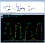
Check the drive signal. This is best done with a capacitor (between 0.1uF and 0.01uF) connected across the pin 1 and 3 FET solder pads.
Confirm that all gate resistors are within tolerance.
Check the drive signal. This is best done with a capacitor (between 0.1uF and 0.01uF) connected across the pin 1 and 3 FET solder pads.
Are the ps fets the 3205's?Pull all of the PS FETs and
Confirm that all gate resistors are within tolerance.
Check the drive signal. This is best done with a capacitor (between 0.1uF and 0.01uF) connected across the pin 1 and 3 FET solder pads.
are the gate resistors the ones directly in front of the 3205's?
do I need to lift a leg on the resistor or can they be checked in circuit?
I do not have any capacitors laying around as I dont normally do circuit diagnostics like this.
will my 10a supply be enough to power it?
I currently do not have a signal generator, and do not want to risk using my phone and having a voltage get back fed into it destroying the amp in my phone.
Yes, the 3205s
Yes, the 47 ohm resistors are the gate resistors.
After the 3205s are out of the board, there will be nothing connected to one terminal of the resistors so they can remain soldered in the board.
10 amp should be enough without the FETs in the circuit?
Why do you need a signal generator?
Yes, the 47 ohm resistors are the gate resistors.
After the 3205s are out of the board, there will be nothing connected to one terminal of the resistors so they can remain soldered in the board.
10 amp should be enough without the FETs in the circuit?
Why do you need a signal generator?
When you mentioned checking the drive signal to me implies i have to drive a signal into the amp and see how it looks? I dont do amp repair, i know basically nothing on how they fundamentally work.Yes, the 3205s
Yes, the 47 ohm resistors are the gate resistors.
After the 3205s are out of the board, there will be nothing connected to one terminal of the resistors so they can remain soldered in the board.
10 amp should be enough without the FETs in the circuit?
Why do you need a signal generator?
is the drive signal checked on pin 2 of the 3205?
The drive is checked on pin 1 of the FET. Pin 2 is 12v and pin 3 is ground.
Do you have a junk amp that you could pull a small capacitor out of? The capacitor won't be harmed so you could pull it from any amp, even this one.
The drive signal is generated by the TL494(?) in the power supply.
Do you have a junk amp that you could pull a small capacitor out of? The capacitor won't be harmed so you could pull it from any amp, even this one.
The drive signal is generated by the TL494(?) in the power supply.
Nope, i dont hoard amps, especially dead ones. when i get the fets out ill get a picture of the waveform(s).The drive is checked on pin 1 of the FET. Pin 2 is 12v and pin 3 is ground.
Do you have a junk amp that you could pull a small capacitor out of? The capacitor won't be harmed so you could pull it from any amp, even this one.
The drive signal is generated by the TL494(?) in the power supply.
Without loading with a cap, the waveforms can be misleading. Better than nothing but barely. When you order parts, order a cap so you can double-check before installing the new FETs.
When in this business and there are so many parts like terminal blocks, transformers, inductors and other difficult-to-get parts, you keep them out of a way to survive. I'm no longer in business but I keep them to use as a reference when I need to see what various waveforms that I haven't needed previously look like to help for those who need help.
Some people keep them with an intent to repair them later.
Hoarding would seem to indicate mental illness.
Eh, i mean, i use the term hoard loosely. theres hoarding parts, then theres hoarding parts. ive got way more parts for the 1980-88 toyota tercel, such as intakes and exhaust manifolds -- parts ill never need, but its nice to have just in case.Without loading with a cap, the waveforms can be misleading. Better than nothing but barely. When you order parts, order a cap so you can double-check before installing the new FETs.
When in this business and there are so many parts like terminal blocks, transformers, inductors and other difficult-to-get parts, you keep them out of a way to survive. I'm no longer in business but I keep them to use as a reference when I need to see what various waveforms that I haven't needed previously look like to help for those who need help.
Some people keep them with an intent to repair them later.
Hoarding would seem to indicate mental illness.
ill order a few fets, and a cap (what size and voltage rating?) however i may just replace the one bad fet and see if it powers up, and if it doesnt, deal with the consequences later.
Will my 10a supply be able to handle the idle current of the amp with all the fets installed?
You need to replace all of the PS FETs if you want the best chance at being reliable. If it's run hard, you need to replace all of them. They should also all have the same date code to help ensure that they have a good chance of being closely matched. If you need 8, I'd order at least 12. If all won't be able to match, at least try to get the ones in each bank to match.
I don't know if the 10 amp supply will be enough. Some JL amps will trigger the low-voltage protection on startup if there is insufficient. I don't know how sensitive this amp is. When you connect it to a higher current supply (in the vehicle) insert a 15 amp fuse in the B+ line to power it up and confirm basic, low-power operation.
The cap will never see more than 15v. A 50v cap is good enough. The waveforms show approximately what you can expect to see with whatever value cap you order.
Attachments
gotcha.You need to replace all of the PS FETs if you want the best chance at being reliable. If it's run hard, you need to replace all of them. They should also all have the same date code to help ensure that they have a good chance of being closely matched. If you need 8, I'd order at least 12. If all won't be able to match, at least try to get the ones in each bank to match.
I don't know if the 10 amp supply will be enough. Some JL amps will trigger the low-voltage protection on startup if there is insufficient. I don't know how sensitive this amp is. When you connect it to a higher current supply (in the vehicle) insert a 15 amp fuse in the B+ line to power it up and confirm basic, low-power operation.
The cap will never see more than 15v. A 50v cap is good enough. The waveforms show approximately what you can expect to see with whatever value cap you order.
does this order look good? it uses 6 PS FETS. Figured ill also order the caps, and install all the caps at once so i dont have to move the same cap 6 times.
if the waveform looks good with the caps, ill take it back to my buddy and have him try it out.
Attachments
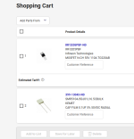
Those look like digikey part numbers so they look OK. Did you check the gate resistors after removing the FETs?
I'd suggest ordering a few more. If you don't get the enough to get matching parts, it may or may not be OK. The cost difference is insignificant, considering what he'd have to pay if he sent it to JL or had a shop repair it.
You don't have to solder the cap in place, you'll clearly see the difference when you make contact. It will go from a perfect square wave (assuming that you've already seen that after removing the FETs) then to the waveforms that were posted.
Update and looking for input --
Got the PS Fets out, had to cut the legs and use 2 soldering irons to get them out. . .
All the new fets appear to be from the same batch.
All resistors are with .5ohm of 47
When checking pin 1 with the cap across pin1 and 3, on the first three sets, Q704 705 706, I am getting ~800mV. Q707 708 709 are ~1.1V
Is this good?
If not, do i need to adjust scope settings, or proceed checking other parts of the amp?
If good, am I safe to install the new ps fets?
- Home
- General Interest
- Car Audio
- JL Audio XD700/5 Repair