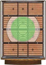
Wrong. Green area is FULL RANGE, White is FULL RANGE with some low pass, All the rest is BASS/MIDRANGE with more low pass.Just make things more clear on bass segments and panels.
Green are the delay rings only above 1 kHz.
White is mid-bass.
All the rest is bass.
This is a 4 panel model, for 6 panel models add an extra bass panel on the top and the bottom.
Never looked at it this way, but I think you got a point. The very center of the mid/high area is directly on the xformer outputs, so full range.Green area is FULL RANGE, White is FULL RANGE with some low pass, All the rest is BASS/MIDRANGE with more low pass.
Hmm.
The only 'real' lowpass I see is at the end of the transmission line; still not much of a low pass with those 300k resistors.
The transmission line delays the wave but doesn't low-pass it, does it?
Or maybe the panel segment capacitances act as progressive low passes along the transmission lines.
Jan
Attachments
Last edited:
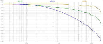
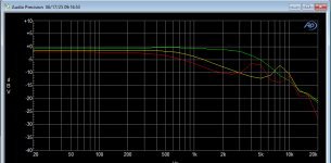
I did a quick sim on Hans Polak's model for the '63, measuring the frequency response at several places along the transmission line, so at several sections of the panel. That appears to confirm the fact that most of the panel works full range, with a drop of some 5dB at higher frequencies. The black, lower curve, is at the final bass panel drive and indeed that is low passed. Enlightening (for me at anyway).Never looked at it this way, but I think you got a point. The very center of the mid/high area is directly on the xformer outputs, so full range.
Hmm.
The only 'real' lowpass I see is at the end of the transmission line; still not much of a low pass with those 300k resistors.
The transmission line delays the wave but doesn't low-pass it, does it?
Or maybe the panel segment capacitances act as progressive low passes along the transmission lines.
Edit: x-axis is 20Hz to 20kHz.
Jan
Attachments
 Thread split from here - https://www.diyaudio.com/community/threads/quad-esl63-dust-protection-comparative-testing.427931
Side conversations can be a welcome part of a thread, sometimes a new thread can be even better.

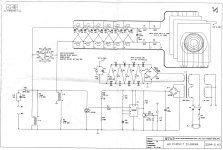
I have this ESL63 dummy load that I used for the development of my direct drive amp.
It consists of a transmission line assembly, with capacitors representing the various segment capacitances soldered between the appropriate points.
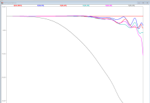
What I would like to do is compare measurements of the frequency responses at the various points on the dummy load with the results of the simulations using the Polak model as shown above.
A quick and dirty check at a few points looks like I'm on the right track (see attachment; compared with post #5), but one thing I am unsure of.
How would the actual air load on the diaphragm impact the frequency response of the transmission line assembly?
Would that change results significantly?
Jan
It consists of a transmission line assembly, with capacitors representing the various segment capacitances soldered between the appropriate points.
What I would like to do is compare measurements of the frequency responses at the various points on the dummy load with the results of the simulations using the Polak model as shown above.
A quick and dirty check at a few points looks like I'm on the right track (see attachment; compared with post #5), but one thing I am unsure of.
How would the actual air load on the diaphragm impact the frequency response of the transmission line assembly?
Would that change results significantly?
Jan
Attachments
The transmission line delays the wave but doesn't low-pass it, does it?
It's a damped transmission line that also acts as a low-pass filter to reduce problems due to edge effects (due to the finite size of the ESL 63). That's what the shorted windings of the coils are for. Peter Baxandall wrote about it in a chapter in a book about loudspeakers long ago.
Yes, chapter 3 IIRC in this book:
Jan
Loudspeaker and Headphone Handbook
English edition by John Borwick (Editor)Jan
- Home
- Loudspeakers
- Planars & Exotics
- Detailed operation of the QUAD ESL63