Hello all I'm trying to finish my TSE build that multiple moves and other real life stuff interrupted. It is the original TSE board which has been populated for a couple of years waiting to be put in a chassis and wired up. It has been set up for 45 tubes.
I have a few simple questions that will help me finish this project.
1-Does the choke get wired directly to R4 pads?
( yes wired in place of R4)
2- Do I need to change C4 if i add the choke? it is currently 47uf 450v and my transformer is 540ct
3-Are there pads to connect the external run cap? I'm a little fuzzy as to where to connect it to the board.
( found in parallel with C5 )
4-and finally while going over the assembly manual I read that R6 was changed to a 6.5w resister, I have a 5w one in my board. I plan to replace it but I am having trouble finding a 6.5w can I use a 7w without causing issues?
( nevermind found a 6.5w )
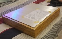
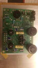
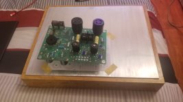
here are some pics of my board and its soon to be new home. The chassis was my first attempt at veneer so its not perfect. Top plate is 1/8in aluminum which I plan to polish.
Edited due to finding the answers on Tubelab website. Only 1 question left.
I have a few simple questions that will help me finish this project.
1-Does the choke get wired directly to R4 pads?
( yes wired in place of R4)
2- Do I need to change C4 if i add the choke? it is currently 47uf 450v and my transformer is 540ct
3-Are there pads to connect the external run cap? I'm a little fuzzy as to where to connect it to the board.
( found in parallel with C5 )
4-and finally while going over the assembly manual I read that R6 was changed to a 6.5w resister, I have a 5w one in my board. I plan to replace it but I am having trouble finding a 6.5w can I use a 7w without causing issues?
( nevermind found a 6.5w )
here are some pics of my board and its soon to be new home. The chassis was my first attempt at veneer so its not perfect. Top plate is 1/8in aluminum which I plan to polish.
Edited due to finding the answers on Tubelab website. Only 1 question left.
Attachments


Last edited:
The veneer looks lovely, is it knotty maple?
Looking at your pictures, will the depth of the PCB be too great for the plinth with the extenders on one side, and the caps on the other?
The driver tube, 5842, is a bit 'twitchy' due to its original purpose and characteristics. I tried to accomplish the same thing as you, but in the end created an opening on the chassis for the driver and adjustment potentiometers. I moved the 4-pin sockets and rectifier sockets to the top plate. (the 300Bs are now symetrical wrt the driver tubes). Major surgery on the PCB will be a bit of a fiddle, but it does swing down for access, the way I attached the 300B sockets. This is the trial fitting, it is like yours, still languishing waiting to be finished since I haven't got the right power transformer, and I need to clear the deck first.
Regarding the 47uF capacitor, that is dictated by the rectifier and is about the top value for a GZ34. Lower values can be used to reduce the B+. What was your thinking there?
Good catch, but i am going to put feet on the plinth to raise it up 2 inches so it will fit.Looking at your pictures, will the depth of the PCB be too great for the plinth with the extenders on one side, and the caps on the other?
I was going to use a 5ar4 in it. The reason i asked was due to something i read on the tibelab site about possibly needing to change the cap if you add the choke. It was 2 years ago that i populated the board so i can't remember if i already got an answer from George.Regarding the 47uF capacitor, that is dictated by the rectifier and is about the top value for a GZ34. Lower values can be used to reduce the B+. What was your thinking there?