I have one of these resistor ladder relay stepped attenuators, Patrick uses them in his own implementation in the F5 preamp.
Seller I used.
I just found this on AliExpress:
£56.81 | Hiend Remote Volume Potentiometer 2X 50K Stereo With Dale Resistors (B7-2)
https://a.aliexpress.com/_EzOLzhU
Some better pictures on the F5 preamp thread
Post in thread 'The F5 Preamp 2024' https://www.diyaudio.com/community/threads/the-f5-preamp-2024.419289/post-7830825
I'm struggling with the remote not working (from new,). As delivered I noticed there wasn't the 3 pin cable or IR receiver delivered. Communication with the seller on AliExpress assured me that the new display board has the IR on the display board. But it wasn't working.
Remote flashes red when I press the buttons. Seems the same remote as seen in Fran's hands on the F5pre video.
I've tried a different IR receiver

And used a 3 way ribbon to connect to the 3 way connector on the W1 board. The led on this KY-022 board flashes as I press the buttons on the remote, so it is getting the signal, but still no joy.
The seller has recommended I try a new LED in the original position on the display board which I am waiting to come from China. I was told it is LF0038M but I can only find references to it on AliExpress so that's where it's coming from.
Not certain it is going to help. Any other way to check all this. The remote control is a bit of a deal breaker as I want to put my streamer into 100% volume output mode and not use the digital volume control in that .
A few more pics I took and sent to the seller


Seller I used.
I just found this on AliExpress:
£56.81 | Hiend Remote Volume Potentiometer 2X 50K Stereo With Dale Resistors (B7-2)
https://a.aliexpress.com/_EzOLzhU
Some better pictures on the F5 preamp thread
Post in thread 'The F5 Preamp 2024' https://www.diyaudio.com/community/threads/the-f5-preamp-2024.419289/post-7830825
I'm struggling with the remote not working (from new,). As delivered I noticed there wasn't the 3 pin cable or IR receiver delivered. Communication with the seller on AliExpress assured me that the new display board has the IR on the display board. But it wasn't working.
Remote flashes red when I press the buttons. Seems the same remote as seen in Fran's hands on the F5pre video.
I've tried a different IR receiver
And used a 3 way ribbon to connect to the 3 way connector on the W1 board. The led on this KY-022 board flashes as I press the buttons on the remote, so it is getting the signal, but still no joy.
The seller has recommended I try a new LED in the original position on the display board which I am waiting to come from China. I was told it is LF0038M but I can only find references to it on AliExpress so that's where it's coming from.
Not certain it is going to help. Any other way to check all this. The remote control is a bit of a deal breaker as I want to put my streamer into 100% volume output mode and not use the digital volume control in that .
A few more pics I took and sent to the seller
The 38 it the part number probably means the part is a 38khz receiver. If you have an oscilloscope see what the output pin of the IR receiver looks like. you should have a pulse train. If nothing then replace the receiver. Make absolutely sure the power and ground is on the correct pins, they damage easily. Good luck.
We have used at least 4 of these and never have any problems.
In fact, we just finished a new preamp soon to be published using the same.
Any 38kHz IR receiver should work.
You need to make sure you connect the pins correctly.
The same package has 2 different pinouts, depending on part number.
The ones we have use separate 3-way cables to connect to the IR receiver.
Probably an older version.
Patrick
Attachments
Last edited:
Hi Jim, firstly to make things clear. I am no way affiliated to the aliexpress shop nor the original designer.
I am a friend of Patrick who has helped Patrick communicate and purchase of the said step pots used in his Pre-Amps, even requested for custom firmwares. From my communication with him, the seller is very passionate about his product and money is not his only goal.
I am assuming that you are aware aliexpress is a 3rd party drop shipper. They are not the original developer
I had shared your situation with the seller. He is willing to support you but being a Chinese, there will be difficulties in communicating with him directly.
As such, he suggested you ask the alishop for exchange.
If you can communicate in mandarin or some one near you can, I can help you get his contact and you mail the module back to him. He is willing to fix it.
In fact, that’s the first thing he asked. Send it back and he will take a look.

Thanks both for your help. I have had a PM from Fran aswell confirming that one he has won't work with the onboard IR, but using a separate one with 3way ribbon cable between display and main board it does. I have tried this and swapping the original IR but still to no avail.
I'm not sure I can communicate in Mandarin but returning for a fix was on my mind. I would like to use this. I understand the AliExpress seller isn't the developer. I can pursue a return/refund but I don't really want to do that!
Shall do some more tests for sanity sake. I was disappointed that trying both the external iR and swapping out the onboard for new didn't fix it. The standalone one with an indicating LED did flash as I pressed the remote, but didn't illicit anything from the module.
The first thing you should check is whether all other functions work as intended.
Then it is just a matter of the remote receiver.
You can contact cloud85 to see if you can return it to the original developer directly.
He is very good to work with, in our experience.
Alternatively, just return to AliExpress for a full refund.
We'll see if we can get one for you from the OEM directly afterwards.
What is the resistor value, 50k or otherwise ?
Patrick
I think I'm going slightly stupid here but I just rigged it all up again but this time new batteries in the remote. With the existing batteries it was flashing the output indicator LED. But fresh batteries and it is working with the (replaced) onboard IR.
Fran check the orientation of your display board IR. Pretty sure mine was in backwards. The flat side should be 'outboard', not next to the display as mine was.
All a bit strange and I hope it keeps working , but for now...👌🏻🤞🏻.
Thanks for all the help. I knew Patrick and Fran would have knowledge of this but I specifically didn't want to bother you guys with this as it isn't your problem to resolve, but I am very grateful and humbled you both reached out. And to cloud85 for potentially being a very helpful contact.
I managed to get this into my Salas DCG3 preamp yesterday. Quite a bit of faffing about. ! Originally I had a DACT type 20k pot onboard the I-Select input board. Wires the W-One up with short solid copper wires. Remotely mounted the MCU board.
Having a few strange issues which I need to resolve. First point I noticed I have a slight crackle/distortion on certain frequencies. Noticed first on piano notes. Hopefully just a signal wire/installation issue.
Second issue is a bit more tricky maybe. Going up through the volume it is dead silent, but once I go from 64 to 65, it starts to buzz through the speakers and at the same time of this, the LCD gets slightly brighter. Stays this way until I get to (forgot the value) step and then it changes again to a slightly lesser buzz.
It isnt lost on me that 64 is half of the 128 steps, so maybe it changes to a different relay(s?)at that midpoint point.
I also seem to have a strange 'phasey' effect, music seems to 'phase' between the speakers, almost making you feel uneasy and like there is a suckout in some frequencies of a high Q...strange.
Seems a lot brighter in presentation, maybe that is the result of going from 20k to 50k.
So it is in and working, but I'm not out the woods yet!
Some pics or it didn't happen as they say! LCD just rested in for now but it kinda looks cool 'ghosting' through the semi opaque lid. It is too garish for me to put in the front panel, so I'm considering options!
A couple of things to check:
1. You can supply eg 5V into the board and measure output to make sure all steps are working correctly from ~0mV out to 5V out. (with it disconnected from DCG3)
2. Double check wiring from front panel to attenuator if you haven't checked already.
3. R15 and R31 are just jumpers?
4. Grounding - the standoffs on the attenuator board are connected to signal ground which is a bit counter-intuitive. Important just for figuring out where you are going to do signal ground to chassis ground.
5. He says in his sheet (did you get any instruction sheets?) that while digital and signal ground are separate, the digital ground should be connected to chassis earth - the rotary encoder is connected to the w-one neg terminal but if you haven't grounded that (yours looks like a plexi front panel) it might be worth trying.
If all that checks out then I can only think of hooking up a signal generator and scope and looking at output.
Are you sure your 5V supply is capable of delivering the current to drive 8 relays ?
As said, we never have had any issues.
So it is certainly not a design issue.
I would try to have it tested off board, with the MCU board in the assembly (not remote), to make sure everything functions as they should.
You can just apply a DC ( or AC if you have a functions generator) voltage at the input, and measure output with a DMM.
Patrick
Thanks Fran and Patrick. A lot of that is all new information for me so some good points for me to check. I didn't get anything as regards instructions.
Fran do you mean R15 and 31 on the attenuator. ? I did notice some 0r in there I think.
Definitely worth me checking earthing as I've done nothing other than connecting the two halves of the attenuator/MCU board back together and the supplied ribbon to the (physically floating) display board.
So there is hope in all this and yes I agree I doubt anything design wise, just implementation!
I see the design has changed as on the Ali sales page there is a diagram for using the peripheral wiring locations for in/out/and and they have been revised on this later iteration.
Thanks again
R15 and 31 are indeed 0r.
Patrick quite possibly not. I am taking regulated 12v from the Salas In select and using 317 to drop to 7v. The trafo for all that isn't particularly big and it is obviously also doing the relays on the input board.
Do I GND the encoder board using the standoff points?.
Thanks 🙏🏻
Patrick quite possibly not. I am taking regulated 12v from the Salas In select and using 317 to drop to 7v. The trafo for all that isn't particularly big and it is obviously also doing the relays on the input board.
Do I GND the encoder board using the standoff points?.
Thanks 🙏🏻
Last edited:
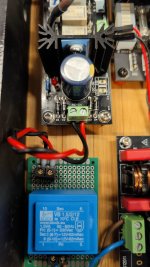
Picture in your post #1 shows that there is a red DIL jumper next to the green screw terminal for power supply.
This jumper should only be in place when you are supplying 5V.
If you supply 7V, the jumper should be removed, as it bypasses the on- board 7805.
The problem of dealing with AliExpress dealers.
You don't get all the information you need.
Patrick
This jumper should only be in place when you are supplying 5V.
If you supply 7V, the jumper should be removed, as it bypasses the on- board 7805.
The problem of dealing with AliExpress dealers.
You don't get all the information you need.
Patrick
Power it off a bench supply first Jim and see if that sorts the issue.
FYI - using the camera option in google translate on your phone is a big help and can live translate the Chinese text. I'll copy what I have here on paper and pm you with it. Mostly its covered now in these posts.
FYI - using the camera option in google translate on your phone is a big help and can live translate the Chinese text. I'll copy what I have here on paper and pm you with it. Mostly its covered now in these posts.
There are two different things to watch on grounding here:Do I GND the encoder board using the standoff points?.
Thanks 🙏🏻
1. Signal ground is connected to the standoffs of the relay stack. So if that is connected to chassis ground you could get noise or hum if you also have signal ground connected elsewhere to chassis ground.
2. The digital power ground (the 7V or 5V mentioned above). That -Vin should be connected directly to chassis ground. For most people that will be at the rotary encoder mounted on a metal front panel. But from the look of yours its an acrylic front panel. I would test by running a short wire from the -in on the rotary encoder board to chassis ground.
But first things first - remove that jumper if you are giving it 7V, or keep it in place and feed 5V. Then check for sag in the power line as you work the attenuator through its range. Given what you mentioned above about the display being dim and then getting brighter makes this something to fix.
- Home
- Source & Line
- Analog Line Level
- Help with W-One ladder relay attenuator remote control