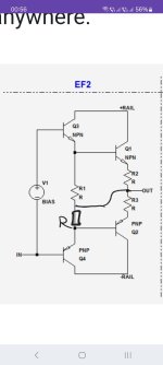
Reading up on different output stage topologies again, I've had this strange idea coming to my mind. On the EF3-topo, each driver transistor is connected to the opposing rail with a separate resistor, determining the idle current. What if I were to replace each resistor with a simple constant current source?
While the EF3 doesn't seem to be all that popular and widespread, I've never even seen an "EF3.5" anywhere. Is there anything severely wrong with it that didn't occur to me yet? Any thoughts / ideas / sources? I'd like to read up on any previous work, if there happens to be something published anywhere.

While the EF3 doesn't seem to be all that popular and widespread, I've never even seen an "EF3.5" anywhere. Is there anything severely wrong with it that didn't occur to me yet? Any thoughts / ideas / sources? I'd like to read up on any previous work, if there happens to be something published anywhere.

You don't need R8/R11 in your "3.5" version, they are redundant.
One practical consideration regarding the use of a CCS is that its output transistor could go into saturation when the output gets close to the supply rail. The saturation voltage depends on the CCS design. It can take some time for a CCS to recover from going into saturation and that could cause problems as well.
One practical consideration regarding the use of a CCS is that its output transistor could go into saturation when the output gets close to the supply rail. The saturation voltage depends on the CCS design. It can take some time for a CCS to recover from going into saturation and that could cause problems as well.
Yes they are; I've just made a quick sketch to bring the idea across.
I'll try to set up a more serious simulation when I have some time (and spoons).
Thanks for your input!
I'll try to set up a more serious simulation when I have some time (and spoons).
Thanks for your input!
Mark - what you say is true, but on a continued large signal the junctions rectify the bias and the bias can change- a dynamic signal-dependent effect. I'm sure you are aware that Bob Cordell recommends using smaller resistors rather than a capacitor, but says it is a choice. I tend to use lowish value resistors within what I think the driver dissipation can tolerate with a small capacitor.
In your first circuit there is no speed-up capacitor across R1.
The others could probably benefit from them too.
A speed-up cap helps to remove stored-charge from the output devices and reduce switching distortion.
I have omitted it here for brevity; others have written about that extensively.
What would be the difference in connecting Q1, Q2 bases with two resistors to the output instead of one resistor to each other . ?
I've seen this approach too.
Sorry for the bad sketch I'm on my phone right now.
That'd be the classic Emitter-Follower Type I then. Douglas Self describes all three types in his book.
Thanks fod the clarification.That'd be the classic Emitter-Follower Type I then. Douglas Self describes all three types in his book.
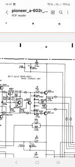
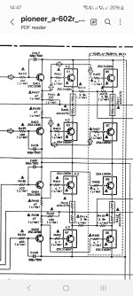
Found another " weird " approach in some Pioneer amps . Using two resistors between the bases and the middle point with another resistor to output.
Attachments
- Home
- Design & Build
- Electronic Design
- EF3 output stage with CCS drivers?