I am intrigued enough by the Berning ZOTL amp to actually try and build one. But before I do a working LTSpice model to understand the design was an necessity for me. So I created a model that matches his patent. I am sure there is many stuff left out of the patent that is important but discovering those in a simulation beats finding out on the bench. So this first attempt is an idealized model, switches instead of FETs, idealized transformers, but a real tube model (6NJ6 screen driven). So being totally new to ZOTL and screen drive this may be an interesting journey. The model does work (I think).
Next steps is to optimize ideal model then bit by bit put in real components....


Next steps is to optimize ideal model then bit by bit put in real components....

Update: I built out the model a little more with a 6N1P phase-splitter and mosfet drive for the 6AV5 screens. Still mostly idealized with a few real components sneaking in. Simulating decent performance so far, now trying to get more power out. Simming to 6W before distortion. Should be able to get at least 20W out of a PP 6AV5.


At the point where I have a useful (I think) functional ZOTL spice model. Added some feedback and can get a pretty nice sim of a 6AV5-like output screen driven. Operating points not optimized but trial and error picked some. Below is FFT of 1W out with an output bias current between 5 and 10ma.

Now I suspect not many have played with the ZOTL architecture. But I have some questions to those that may have experience. (@kamonjira).
1. What impedance ratio from primary to secondary rectifier chain is a good place to start. I have simulated with ~5-6K secondary impedance in this model assuming a 8ohm load?
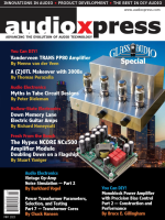
2. With screen driving this tube in ZOTL achitecture how much plate voltage peaks can be tolerated. Below are the plots of the plate voltage at 1W out.

Now I suspect not many have played with the ZOTL architecture. But I have some questions to those that may have experience. (@kamonjira).
1. What impedance ratio from primary to secondary rectifier chain is a good place to start. I have simulated with ~5-6K secondary impedance in this model assuming a 8ohm load?
2. With screen driving this tube in ZOTL achitecture how much plate voltage peaks can be tolerated. Below are the plots of the plate voltage at 1W out.
Very nice project, well done. I will follow with interest.
I did an article/interview for AudioXpress about this technology, still not fully convinced that it is beneficial for the audio reproduction, but it is a very smart technique.
Thanks.
Jan
I did an article/interview for AudioXpress about this technology, still not fully convinced that it is beneficial for the audio reproduction, but it is a very smart technique.
Thanks.
Jan
Do you have a link for your article? I would enjoy reading it. I am initially curious about to learn (sim + hands on) the plusses and minus of the various impedance matching methods available.
1. Traditional ubiquitous large iron transformers (~75 years of continuous development)
2. ZOTL - switching tech. Not alot of DIY or open source development
3. Traditional OTL - Lots of DIY, is traditional OTL development at the end of its development arc?
1. Traditional ubiquitous large iron transformers (~75 years of continuous development)
2. ZOTL - switching tech. Not alot of DIY or open source development
3. Traditional OTL - Lots of DIY, is traditional OTL development at the end of its development arc?
The ZOTL preferred high impedance. The 80 time turn ratio has been mentioned in Berning's ZH210(Seigfried SV811-10).
6AV5 has special absent pin in their base that can withstand 5500 V peak. From my Z10 clone, the 300 V rating of EL84 can accept 450 V_p-k without any problem.
Normal pp tube amp is parallel dc-series ac type amplifier, but the ZOTL is series dc-parallel ac type ones.
6AV5 has special absent pin in their base that can withstand 5500 V peak. From my Z10 clone, the 300 V rating of EL84 can accept 450 V_p-k without any problem.
Normal pp tube amp is parallel dc-series ac type amplifier, but the ZOTL is series dc-parallel ac type ones.
Thank you. I noticed in the LTSpice sims that better performance was achieved with much higher impedance (turns ratio) that I was familiar with but was concerned about the peak ac voltages seen on the plate with signals. Significantly higher than with normal OT's in PP.
Did you ever find the cause of the voltage/power loss? Having to go to an 80:1 turns ratio spells doom to me. All those xfmrs will have cumulative leakage reactance and turns distr. capacitance effects, suffered at the carrier freq. no less. But those parasitic effects aren't even modeled in the simulation ( k=1, C=0 ) Then there is the lack of HV safety, and WAY too many parts with HF radiation, shielding, HF filtering, absolute need for N Fdbk to get Zout down.....
There are other ways to do impedance conversion, but each has it's own drawbacks. Generally unacceptable for audio.
Greinacher / Cockroft-Walton multipliers. Delay time for large ratio, and still switch-mode. Can be made resonant at switching freq. to eliminate parasitic C buildup.

Piezo-electric. Non-linear and mechanical resonances.
Homopolar generator. Moving parts.
The DC to light xfmr. Bifilar metal strips as transmission lines, wound so each 1x section is bifilar to the next and the previous 1x section, but no proximity beyond that. Strips get narrower toward HV / HiZ end. Wound on magnetic core to reduce size. Too expensive, bulky, heavy. Derives from redundancy reduction of the common mode choke scheme below.
Multiple common mode chokes, series connected on primary sides, parallel connected on secondary sides. Can be same core, but lots of wire.
Multiple 1:1 bifilar xfmrs, series connected on primary sides, parallel connected on secondary sides. Can be same core, but lots of wire.
Permalloy ribbon or core covered multi-wire cables, too bulky.
Multiplying current mirror(s), bipolar or Mosfet, N and P type mirrors can be cascaded for their product. Requires transistor matching. All SS power output, very linear, efficient, cost effective. The best performer by far. Unacceptable to tube purists.
Many other schemes, all have some issue.
There are other ways to do impedance conversion, but each has it's own drawbacks. Generally unacceptable for audio.
Greinacher / Cockroft-Walton multipliers. Delay time for large ratio, and still switch-mode. Can be made resonant at switching freq. to eliminate parasitic C buildup.
Piezo-electric. Non-linear and mechanical resonances.
Homopolar generator. Moving parts.
The DC to light xfmr. Bifilar metal strips as transmission lines, wound so each 1x section is bifilar to the next and the previous 1x section, but no proximity beyond that. Strips get narrower toward HV / HiZ end. Wound on magnetic core to reduce size. Too expensive, bulky, heavy. Derives from redundancy reduction of the common mode choke scheme below.
Multiple common mode chokes, series connected on primary sides, parallel connected on secondary sides. Can be same core, but lots of wire.
Multiple 1:1 bifilar xfmrs, series connected on primary sides, parallel connected on secondary sides. Can be same core, but lots of wire.
Permalloy ribbon or core covered multi-wire cables, too bulky.
Multiplying current mirror(s), bipolar or Mosfet, N and P type mirrors can be cascaded for their product. Requires transistor matching. All SS power output, very linear, efficient, cost effective. The best performer by far. Unacceptable to tube purists.
Many other schemes, all have some issue.
Last edited:
I get 'decent' sims with a much lower turns ratio putting the plate impedance around 10-12K for the 6AV5, ~35 turns ratio over a string of 6-8 transformers. Like Berning usually does it.
Here are a few more impedance converter schemes, some borderline crazy.
Electromagnetic solenoid compressed, carbon disk pile regulator. Used on Mil Gen Sets for voltage regulation. Also used for sewing machine speed control and railroad car lighting control. Inefficient, slow, noisy.
Plasma TV screen OTL tube. Bulky.
Series LEDs or Laser to paralleled photovoltaic or photo-resistive cells. Inefficient, slow?
Radar pulse tubes for PWM class D. Yuk.
Stacked current xfmrs. with wound low turn secondary. Or use a 240V+ Variac unit.
Utility pole xfmr. Heavy.
Industrial control xfmrs. 600VCT Watch out for high temp rise units (low turns, inefficient high magnetizing current, coarse non-grain aligned laminations )
Large Ferrite toroids Fair-Rite 5978008001 6 inch OD, 2.7inch ID, 0.75 inch thk, stack of 4, $300+ each ( ferrite takes 3x the area of steel due to low Bsat) (high initial permeability at zero field: good )
Some Ferrite materials. can be electroplated on, by the way.
Circlotron, Crowhurst Twin-coupled. high quality, more complex
Old hard disk drive actuator for Sub Woofer
Tube current mirror or voltage mirror. Matched OTL type tubes for current mirror. Impractical. ( Aikido front end is a voltage mirror, invented in 1940s. )
Power D/A, impractical with tubes
Darlington and Sziklai (or Complementary Fdbk Pair ) similar to Current Mirrors but gm/gain is temperature sensitive (not good in hot tube Amp )
Two inductors clamped together, one is secondary and CFB winding, other is plate winding, poor
Powdered Iron xfmr. Non functional (low permeability) non-linear (point contacts saturate) there was a thread on this low cost idea once.
OTL class B switcher, 1/2 the tubes and heat, Mosfets change tube polarity, desperation
Required Reading:
US Patent 4614914 by Audio Precision, elegant fix for OT magnetizing current, hysteresis and removing primary resistance. Takes two resistors per output tube. No switching stuff. Low output Z. Can be applied to existing tube Amps. Precedes the Berning patent. Makes a normal tube Amp into an OTL equivalent without extra heat. SE Amps are superfluous.
Last edited:
- Home
- Amplifiers
- Tubes / Valves
- ZOTL LTSpice Model