All,
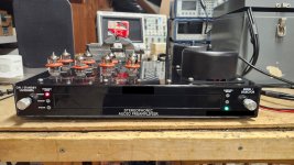
Here is the initial post (more will follow) for a project I wish to share that I have been working on for a while (hence my absence from this forum). It is a vacuum tube preamplifier that essentially marries 1950s technology with that of the 21st century. Here is a list of its primary features:
1. Bluetooth input and audio streaming capability.
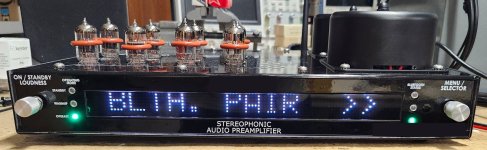
2. Smartphone control with Bluetooth.
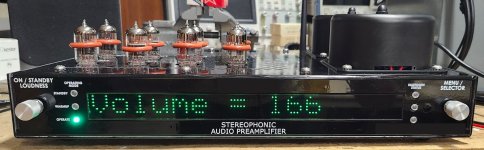
3. Dot matrix RGB display for digital volume control and menu screens.
4. Protection mode for output overload, open tube heaters, and power loss.
5. Software-defined programmable gain (default gain is 12dBV).
6. Tape input, tape monitor loop, and buffered tape output.
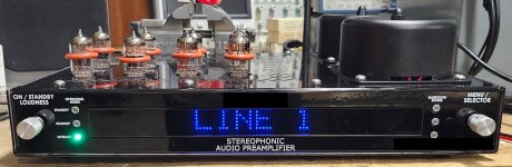
7. Four 20k ohm line level (-10dBV) inputs.
8. Switchable high-impedance buffer (used for high-impedance sources such as ceramic cartridges) makes any line input 1M ohm.
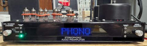
9. 45dBV 47k input impedance RIAA magnetic phono input.
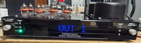
10. Two switchable 6922 direct-coupled line-level outputs can drive 600 ohm loads with 0.01% or less THD. 6N1P tubes produce slightly more distortion.
Audio circuitry:
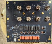
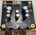
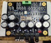
1. All tube circuitry in audio path for line and phono stages.
2. Bluetooth audio signal processing, tape output buffer, and high-z buffer circuits are solid-state.
3. Four 6C45P tubes are used for phono and four 6N1P or 6922 for line.
The software is not complete. I have at least a month of C coding ahead of me to get the Bluetooth streaming/pairing functionality (along with some bug fixes) to work correctly.
Before anyone panics, I must note that the digital circuitry, display, and Bluetooth radio cause no measureable or audably noticable interference (even with the phono input at full volume without the input shorted) in this design.
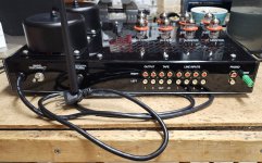
Attached are several pictures of the unit. What do you all think? Once I see some initial opinions, I will post some test results.
Thanks
Here is the initial post (more will follow) for a project I wish to share that I have been working on for a while (hence my absence from this forum). It is a vacuum tube preamplifier that essentially marries 1950s technology with that of the 21st century. Here is a list of its primary features:
1. Bluetooth input and audio streaming capability.
2. Smartphone control with Bluetooth.
3. Dot matrix RGB display for digital volume control and menu screens.
4. Protection mode for output overload, open tube heaters, and power loss.
5. Software-defined programmable gain (default gain is 12dBV).
6. Tape input, tape monitor loop, and buffered tape output.
7. Four 20k ohm line level (-10dBV) inputs.
8. Switchable high-impedance buffer (used for high-impedance sources such as ceramic cartridges) makes any line input 1M ohm.
9. 45dBV 47k input impedance RIAA magnetic phono input.
10. Two switchable 6922 direct-coupled line-level outputs can drive 600 ohm loads with 0.01% or less THD. 6N1P tubes produce slightly more distortion.
Audio circuitry:
1. All tube circuitry in audio path for line and phono stages.
2. Bluetooth audio signal processing, tape output buffer, and high-z buffer circuits are solid-state.
3. Four 6C45P tubes are used for phono and four 6N1P or 6922 for line.
The software is not complete. I have at least a month of C coding ahead of me to get the Bluetooth streaming/pairing functionality (along with some bug fixes) to work correctly.
Before anyone panics, I must note that the digital circuitry, display, and Bluetooth radio cause no measureable or audably noticable interference (even with the phono input at full volume without the input shorted) in this design.
Attached are several pictures of the unit. What do you all think? Once I see some initial opinions, I will post some test results.
Thanks
Attachments
-
 Back.jpg526.5 KB · Views: 320
 -
 Warmup.jpg327 KB · Views: 299
 -
 Volume.jpg258.1 KB · Views: 293
 -
 Top.jpg568.3 KB · Views: 280
 -
 Test Setup.jpg588.5 KB · Views: 285
 -
 Standby.jpg517.5 KB · Views: 290
 -
 Phono.jpg277.1 KB · Views: 287
 -
 Out 1.jpg275.1 KB · Views: 281
 -
 Line 1.jpg271.7 KB · Views: 305
 -
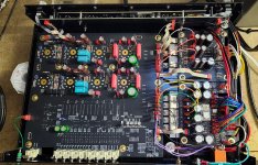 Inside.jpg733.4 KB · Views: 315
 -
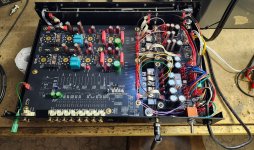 Inside 2.jpg681.1 KB · Views: 320
 -
 Bluetooth (2).jpg292.5 KB · Views: 303
 -
 AUD-1 Bottom 2.jpg818.5 KB · Views: 270
 -
 AUD-1 Top 2.jpg724.8 KB · Views: 274
 -
 VREG 2.png6.4 MB · Views: 256
 -
 VREG 3.jpg597.6 KB · Views: 314
Last edited:

I hope it isn't so but from the pictures I see, glossy paint does not look good (i.e. for such a well-designed circuit). Everything else I like.
Could you explain the buffer for input and tape out you are using (or it's not the right forum) ?
Keep up the good work.
Could you explain the buffer for input and tape out you are using (or it's not the right forum) ?
Keep up the good work.
@savvas
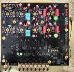
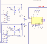
1. I have attached a partial schematic of the volume control and selector switch. The hi-z buffer is simply an op amp that is switched in and out of circuit using the relay K1. When the buffer is in circuit, the input impedance is 1M ohms. When out of circuit, the input impedance is 20k ohms (simply the volume IC).
2. The tape output buffer takes whatever input the selector switch has selected and feeds it into an opamp follower that feeds the tape output.
@petertub
There is no loop circuit or built in tone controls. However, the idea for dual line outputs is to connect external equipment such as active crossovers, slave amplifiers, subwoofers, etc.
Attachments
Last edited:
The preamp is missing both tonecontrols and a loop that gives a possibility to include an external one ?
Inclusion of a switchable loop could be beneficial if any adjustment or filters are needed. A much more
flexible solution then built-in tonecontrols.
Inclusion of a switchable loop could be beneficial if any adjustment or filters are needed. A much more
flexible solution then built-in tonecontrols.
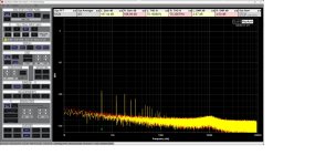
Attached are test results for the line stage and the Bluetooth input. All measurements were taken with a QuantAsylum QA403 Audio Analyzer. The yellow signal represents the left channel and the red is the right.
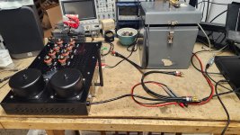
1. Test setup. The audio analyzer was placed inside of a metal carrying case (that once stored 5.25 inch floppy disks) to minimize contamination of 60Hz noise to the measurements.

2. Ambient noise floor. The audio analyzer is disconnected from unit (the 60Hz spike would be much worse without the metal box).

3. LINE 1 input unshorted with volume open. 60Hz noise and harmonics are picked up by the output RCA cable running to the audio analyzer. The noise hump at 10kHz is likely from radiated emissions off my computer monitors or gaming LED illuminated keyboard. The keyboard has caused problems with other pieces of my equipment. My guess is the PWM switching for the RGB LEDs is radiating from the circuit board and/or the USB cable.

4. LINE1 input shorted with volume open. 60Hz energy is essentially unchanged. 10kHz hump is gone.

5. The LINE 1 input is fed with a -10dBV signal at 1kHz with no loading on output. Output is +2dBV. Signal to noise and THD are listed at the top of the chart. The second harmonic is around -98dB on the left channel and -85dB on the right.

5. The LINE 1 input is fed with a -10dBV signal at 1kHz with 600 ohm loading on the outputs. The output THD increases to around 0.01%. The 3rd harmonic magnitude increases from -110dBV to -80dBV on both channels. The second is essensially unchanged.

6. Noise floor with the Bluetooth input selected. The floor increases below 1kHz, with respect to the shorted line input, by about 10dBV.

What do you all think of the results for the line stage portion of this unit? I will post the phono stage results tomorrow.
Thanks
1. Test setup. The audio analyzer was placed inside of a metal carrying case (that once stored 5.25 inch floppy disks) to minimize contamination of 60Hz noise to the measurements.
2. Ambient noise floor. The audio analyzer is disconnected from unit (the 60Hz spike would be much worse without the metal box).
3. LINE 1 input unshorted with volume open. 60Hz noise and harmonics are picked up by the output RCA cable running to the audio analyzer. The noise hump at 10kHz is likely from radiated emissions off my computer monitors or gaming LED illuminated keyboard. The keyboard has caused problems with other pieces of my equipment. My guess is the PWM switching for the RGB LEDs is radiating from the circuit board and/or the USB cable.
4. LINE1 input shorted with volume open. 60Hz energy is essentially unchanged. 10kHz hump is gone.
5. The LINE 1 input is fed with a -10dBV signal at 1kHz with no loading on output. Output is +2dBV. Signal to noise and THD are listed at the top of the chart. The second harmonic is around -98dB on the left channel and -85dB on the right.
5. The LINE 1 input is fed with a -10dBV signal at 1kHz with 600 ohm loading on the outputs. The output THD increases to around 0.01%. The 3rd harmonic magnitude increases from -110dBV to -80dBV on both channels. The second is essensially unchanged.
6. Noise floor with the Bluetooth input selected. The floor increases below 1kHz, with respect to the shorted line input, by about 10dBV.
What do you all think of the results for the line stage portion of this unit? I will post the phono stage results tomorrow.
Thanks
Attachments
So this is a modern version of a receiver.
- What do you intend to use for the streamer? RPI or similar?
- And the dac?
- Will this be a commercial product or will you publish schematics and gerbers at some point?
I applaud your efforts. I would look at completely different cosmetics though. Think more along the line of the Counterpoint styling. 1 or 2U enclosures. No tube's poking through the top. Tube's sitting in horizontal mount inside chassis. Look atthe SA series 3 and 5. Very classy look
I am not sure what is meant by Counterpoint Styling or what the SA series 3 and 5 are. Please be more specific. Also, I am limited in how I can change the chassis due to my circuit board layouts.
The look I was targeting was a neo 1950s theme, black chrome. Furthermore, the 10x32 screws on the top are for a cover for the tubes for pet proofing. I did not order it because tarrifs are making such products artifically expensive.
The look I was targeting was a neo 1950s theme, black chrome. Furthermore, the 10x32 screws on the top are for a cover for the tubes for pet proofing. I did not order it because tarrifs are making such products artifically expensive.
OK I understand the look you are going for and it matches that. Mine is circa mid to late 80s. 1U enclosure tubes inside of chassis. But you can see them through the top. Anyway good job on your design.

@TorroidDoughnut - Very nice work! I have been using relay-switched attenuators in my builds but have been intrigued by the Muses chips (would save money and a fair amount of space). What are your thoughts on this chip? Have you compared sound quality to other attenuator solutions?
@Jaytor
Relay attenuators are my default preference, but the fact they occupy they large amount of space on circuit boards, are expensive, call for hard to obtain resistor values, and elevate the design risk for degraded audio signal integrity, make them not qualify for my designs. Also, some could be annoyed by the typewriter-like sound relay bank switching makes. Furthermore, relay attenuators can have issues with zipper noise.
The Muses chip is essentially switchable resistor ladders on a chip (or the equivalent of a relay attenuator). Per channel, it has a network of two ladders, one for a negative feedback loop to set gain and the other for volume. The chip was designed for op-amp use but I adapted it for vacuum tubes. I cannot distinguish the sound between a regular volume control and the chip. This could be because the chip has no positive gain, or op-amps on it, probably just JFETs to work in place of the relays (hence the negative rail).
What also is nice is the zero crossing detection feature. This prevents the attenuator from changing the volume until the signal passing through it is zero, which helps mitigate zipper noise. Good luck doing that with mechanical relays!
Thanks,
@TorroidDoughnut
Interesting mix of surface mount and through-hole devices. Those PC boards must have been quite the effort to design! Might make it hard though for hobbyists to assemble, but maybe that is not the intent.
I do like the vacuum tubes sitting out in the open on top, the 'inverted cooking pot' toroid covers less so. The red rubber rings around the tubes got to go though!
The front panel design feels a bit incongruent as far as the fonts (thickness, letter spacing ('kerning')) are concerned, and the RGB dot matrix display looks a bit odd. It might be difficult to integrate a display into your desired look. Maybe go for some Nixie-tube lookalike for the display, or a high resolution panel that can emulate smaller dots? Such a display could then also emulate VU meters, or a frequency spectrum display, or whatever you want. But hey, you have to like it, not me!
On the back panel, some spacing between the different groups of RCA connectors would look and feel more organized, but would eat up more PCB length, I assume.
From the measurements, it seems almost but not quite state of the art (which is -115 dB SINAD or such?), and at better than -90 dB certainly good enough. I'm no electronics expert though.
@Gruesome
I designed the boards and assembled them entirely by hand. I have been designing and building boards, both professionally and as a hobby, for a while now. For a typical hobbyist, it is not trivial (especially the quad flat pack), but also not impossible (especially with practice).
The display I did not design. I bought it from Lumex. I agree it is not ideal. I have a design for a display, with twice the resolution, but that is a future project. I will need to buy these assembled because it has 4096 RGB LEDs on it.
If I were rich, I would buy a $50000 audio analyzer. But that QA403 is far superior to my HP8903B.
I meant the amp being certainly good enough, it wasn't a comment on your measurement gear! TomChr did a comparison of the QA403 to an APx525 (or 555?), and also some cheaper options (video), and the QA403 did very well, i.e. not 40 dB worse than a device 40 dB more expensive... The comparison review also on his Neurochrome web site at https://neurochrome.com/pages/measuring-distortion-on-the-cheap .
There are tube preamps (like the Audio Research) that advertise 0.002% distortion without negative feedback, but that probably is into high-impedance loads (100k ohms for their power amplifiers) with an optimal choice of tubes. My unit can do 0.004% or less (depending on tube variance) per image 5 in my previous post into 100k ohms (the input impedance of the analyzer).
As per the 0.01% THD, that is into 600 ohms at 12dB out, a punative load for a tube line stage. If I program the gain to be lower, that will drop. I also have an alternate design that improves those numbers. It requires more tubes so I had to compromise.
There are CLASS D designs that have 10k ohm input impedance or less. I designed my unit to have the capability to drive that kind of amplifier, as well as generally being compatibie with solid-state equipment.
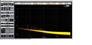
Here is the phono stage data. All measurements were taken at the tape output:
1. Noise floor without input shorted. A -78dbV 60Hz noise and harmonics are picked up by the RCA cables.

2. Phono input shorted. 60Hz noise drops to -85dbV.

3. Phono stage with a 1kHz tone. The gain is 46dBV. THD is 0.005% or less into 20k ohms (the volume control). The signal to noise ratio is -67dbV, with the 6C45P tubes combination I chose, without any signal weighting. The S/N ratio can vary, depending on the tubes, from -60dBV to -71dbV.
With respect to the 60Hz noise, my hypothesis is ground loops are the cause. Along with the RCA cable shields, they form through the audio analyzer and the ground planes of the unit under test. The audio input and output grounds of the analyzer are connected together inside (thankfully they are isolated from the USB interface). Does anyone have any suggestions of a labratory-grade audio transformer I can use to test my ground loop hypothesis? I would be interested to see if I can improve the 60Hz noise spikes.

4. The RIAA deviation, for both the left and right channels, is 0.22dBV or less.


What do you all think?
1. Noise floor without input shorted. A -78dbV 60Hz noise and harmonics are picked up by the RCA cables.
2. Phono input shorted. 60Hz noise drops to -85dbV.
3. Phono stage with a 1kHz tone. The gain is 46dBV. THD is 0.005% or less into 20k ohms (the volume control). The signal to noise ratio is -67dbV, with the 6C45P tubes combination I chose, without any signal weighting. The S/N ratio can vary, depending on the tubes, from -60dBV to -71dbV.
With respect to the 60Hz noise, my hypothesis is ground loops are the cause. Along with the RCA cable shields, they form through the audio analyzer and the ground planes of the unit under test. The audio input and output grounds of the analyzer are connected together inside (thankfully they are isolated from the USB interface). Does anyone have any suggestions of a labratory-grade audio transformer I can use to test my ground loop hypothesis? I would be interested to see if I can improve the 60Hz noise spikes.
4. The RIAA deviation, for both the left and right channels, is 0.22dBV or less.
What do you all think?
That's quite the project! Nicely done.
I'm curious which solution you ended up with for the Bluetooth. Also, which display are you using?
Tom
I'm curious which solution you ended up with for the Bluetooth. Also, which display are you using?
Tom
- Home
- Amplifiers
- Tubes / Valves
- Fully 21st Century Tube Preamplifier