Working on a Kicker KXA2400.1, there doesn't seem to be much info out there on these. Found schematics of the KX (not "A") series, radically different. Powers on, everything looks reasonable, protect light comes on then goes off, draws about an amp once it's stable, no output.
Opening it, found a nice flash mark where a little lockwasher came from somewhere and wandered over to short the positive rail busbar (near the green LED & USB port) to the grounded pressure plate for the rectifiers. The washer was mostly vaporized and the rail is no longer shorted -- the positive rail comes up to voltage fine, but the negative rail is dead.
Also found a blown capacitor in between the two output coils, replaced that, still doesn't work. No other obviously failed components or flash marks from said washer shorting other things before meeting its demise.
Weird power supply architecture, using two non-isolating boost converters instead of the usual transformer. Seems to be asymmetric as well, the positive rail having more transistors and higher voltage rated caps than the negative. And here I thought Rockford was the king of trying to find new ways to patent a switching power supply.
Anyone worked on one of these yet and have any pointers, or perhaps a schematic of it?
Thanks!
If the Kicker tech doesn't see this, post a photo of the board and list the part number of the PS driver IC and the audio output driver ICs.
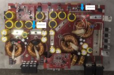
Board photo with location of short and blown cap marked.
Output drivers are IRS20957, power supply ICs are 3843s plus a MP18201 gate driver on the negative side.
The 3843 for the negative rail has ~5V on its FB pin, which is likely what's causing it to not run. Haven't found yet where it's coming from.

Output drivers are IRS20957, power supply ICs are 3843s plus a MP18201 gate driver on the negative side.
The 3843 for the negative rail has ~5V on its FB pin, which is likely what's causing it to not run. Haven't found yet where it's coming from.
Yes. It's likely being driven into protect by an LM358. I emailed the Kicker tech. I rarely email him so I don't know if the email is still good.
What about gatedrive signal on 3843 output? Can u post the pictures of bottom side? What output transistors (at amplifier side) this one use?Weird power supply architecture, using two non-isolating boost converters instead of the usual transformer. Seems to be asymmetric as well, the positive rail having more transistors and higher voltage rated caps than the negative. And here I thought Rockford was the king of trying to find new ways to patent a switching power supply.
In order to achieve ~105 Vdc single (+) mono rail, there are two boost converters. one +75Vdc and one (-) 30Vdc.
I attached your edited photo. Please measure the VDC between the two rails I've pointed out.
Have you check the three mosfets Q19-Q21?
Also as Jack asked check the drive voltage on UC3843 pin 6with a scope if possible has well as Pin 4 sawtooth.
And a screenshot of the bottom side of PCB might be helpful.
Attachments
Jack: The outputs are 076N12N, driven by IRS20957.
Measurement across the indicated rails is 73.6V, the positive side is ~72.5V and the negative is like -0.7. There is sawtooth on both 3843s, but the one for the negative side has ~5.7V on pin 2, which is likely causing it to not run, I think it's being inhibited by something as Perry suggests. The FETs aren't shorted, I'll check if perhaps they're open.
Everything on the positive side seems to be working as expected, but the negative boost refuses to run. Weird that with a microcontroller in there and all, it doesn't notice that and throw protection.
The negative rail is not strongly shorted to anything, it can be made more negative with a (isolated) bench supply, no high current draw, but I didn't go beyond -10V with it, not knowing what it should be.
Nothing obviously shorted or burnt in the output section, aside from that one cap that I replaced. It was visibly burst.
I'll test those mosfets and try to observe any startup behavior on the negative side with a scope tomorrow.
Better (I think) board photos attached, top and bottom.
Attachments


When the washer shorted the neg rail, it's likely that the IRFB3206's where damaged. You will want to check Q17-S4320 and Q18-S5320 and all gate resistors. IC5-18021 may be damaged also.
IC4-LM358 is in the feedback loop looking at the neg rail fed to Pin 2 inverting input. Pin 1 is feeding IC3-UC3843 Pin 2.
IC4-LM358 is in the feedback loop looking at the neg rail fed to Pin 2 inverting input. Pin 1 is feeding IC3-UC3843 Pin 2.
Correction:
The washer shorted the positive rail. I'm a little unclear why this may have damaged the Neg rail mosfets but worth checking them.
It's possible IC4-LM358 has failed
This is not a typical failure and the first time I've seen a floating washer find it's way to that location.
The washer shorted the positive rail. I'm a little unclear why this may have damaged the Neg rail mosfets but worth checking them.
It's possible IC4-LM358 has failed
This is not a typical failure and the first time I've seen a floating washer find it's way to that location.
- Home
- General Interest
- Car Audio
- Kicker KXA2400.1 Power Supply Fault?