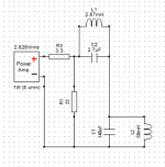
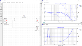
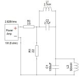
I want to build a load to test amplifier distortion and possible instability into something resembling my Seas A26 two-ways. I don't know what I'm doing, but I came up with this circuit. The impedance plots kinda match, right? Should I be concerned about all the swings in phase?
Attachments

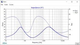
What does the phase look like on the Seas two-ways? If it's similar to your proposed load, then it may be fine as is. Phase swings in real speakers are pretty common and are part of the purpose of the simulated speaker load. I'm not sure what your concern was on this front.
Stereophile's take on the topic (more info at the link - these are just the final images):
https://www.stereophile.com/reference/60/index.html

Stereophile's take on the topic (more info at the link - these are just the final images):
https://www.stereophile.com/reference/60/index.html

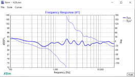
I don't remember where I got these but I believe the woofer and tweeter models were correct for the A26 drivers and used in a series crossover design for the A26. If I understand this correctly (big if), the frequency response plot shows a big phase inversion from the crossover at 1800Hz but the impedance plot of the speaker as a whole is relatively flat in phase. The impedance plot in simulation is way different than the measured one reported in the spec sheet for the A26 (which is the one I posted above) so I am unsure how accurate this simulator is.
I suppose one concern has to do with that giant 50mH choke. Is it going to send a honkin' big EMP back into my amp and test gear when the voltage collapses?
I suppose one concern has to do with that giant 50mH choke. Is it going to send a honkin' big EMP back into my amp and test gear when the voltage collapses?
Attachments
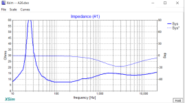

I would check the woofer on its own (just set C1 or R1 to open or drag it out of the circuit). If the impedance phase angle of the woofer is completely flat at zero, it's missing phase data. It looks suspiciously flat over most of the range in your plot.I believe the woofer and tweeter models were correct
You are correct sir, it looks like there is no phase data for the woofer when the tweet is out of circuit. Thank you both for your feedback!
I'm going to build this load simulator more or less as designed then, with some minor tweaks to values for cost/availability reasons.
I, ah, am acquiring a new-to-me amp that has some reputation for oscillating into reactive loads & destroying woofers in the process. I'm building this load to model if this amp is likely to oscillate into my favorite speakers before playing through them. Or at least that's the plan. $30 and a few weekends of insurance. Also some learnin.
Attachments
So I went and built this. When testing an ACA using a distortion analyzer, 1.72V into 8R gets me the published number of 1% distortion at 1kHz and at pretty much any frequency I tried. 1.72V into an ACA loaded with this, I'm reading more like 0.77% distortion. Cool.
Attachments

- Home
- Loudspeakers
- Multi-Way
- Speaker simulator for a distortion analyzer