Building the power supply for my Wolverine and inspired by the incredible build photos from @stuartmp and @danieljw, I decided to learn KiCad and do my own dual full-wave bridge rectifier pcb. I would have used the one from @prasi, but I wanted to use screw terminals instead of quick-connect tabs. That's the nice thing about doing your own -- you can use whatever hardware you prefer. So for anyone who hasn't taken the plunge, I highly recommend it. It's really pretty easy -- KiCad is amazing -- and quite fun. So thank you to @stuartmp, @danieljw, @prasi, and @xrk971 for the wealth of info you've shared in these forums that inspired me to take that plunge.
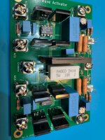
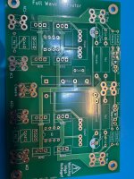
Fwiw, here's what I came up with. It's an active rectifier using the LT4320 Ideal Diode Bridge Controller like @prasi's combined with features that I see in the photo of @stuartmp's dual bridge rectifier pcb. So it's kind of a hybrid between the two. The key features are:
Fwiw, here's what I came up with. It's an active rectifier using the LT4320 Ideal Diode Bridge Controller like @prasi's combined with features that I see in the photo of @stuartmp's dual bridge rectifier pcb. So it's kind of a hybrid between the two. The key features are:
- Dual active rectifiers using the LT4320
- Can use either screw terminals or quick-connect tabs
- Supports a ground lift circuit to connect to chassis ground
- Supports indicator LEDs onboard, offboard, or both
- Supports bleeder resistors
- Supports the RZ/CZ components as on @stuartmp's pcb
Attachments

RZ and CZ decrease the impedance and help reduce noise from the FETs when switching.
As it does no more than a standard bridge rectifier, I must ask why build another 'wheel', it is not possible to reinvent the 'wheel'.
As it does no more than a standard bridge rectifier, I must ask why build another 'wheel', it is not possible to reinvent the 'wheel'.
Cx, Cs and Rs are for a snubbed across the transformer secondary.
The idea is to dampen the ringing of the transformer caused by diode switch off.
Ultimately it is to make the power supply quieter.
See here
Mark's pdf explains quite nicely why and how to use it.
If you have a scope already, I think building a quasimodo is fantastic investment.
The idea is to dampen the ringing of the transformer caused by diode switch off.
Ultimately it is to make the power supply quieter.
See here
A power transformer snubber is a wonderful thing for reducing or eliminating RFI from rectifier-induced LCR ringing. Unfortunately it's a huge pain to design and optimize a snubber. First you have to measure the transformer's leakage inductance and secondary capacitance, at about 100 kHz, which is not especially easy. Then you have to estimate the capacitance of your rectifier(s), which does not always appear on datasheets. Finally you plug these numbers into a formula that spits out snubber values -- and then you hope it's all correct.
Shown here is a little test jig called...
Shown here is a little test jig called...
- Mark Johnson
- Replies: 2,653
- Forum: Power Supplies
Mark's pdf explains quite nicely why and how to use it.
If you have a scope already, I think building a quasimodo is fantastic investment.
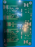
Excellent idea. Thank you! And yes, 2oz copper.You may like to add some chamfers on some of your pcb connections.
Yup, I understand the snubber and use Quasimodo -- it's excellent. My question is about CZ and RZ.Cx, Cs and Rs are for a snubbed across the transformer secondary.
As it does no more than a standard bridge rectifier, I must ask why build another 'wheel', it is not possible to reinvent the 'wheel'.
Lower forward voltage drop than a rectifier. Won’t even need a heat sink with an audio load.
To gain an extra 400mvolts of supply ... not worth the effort or cost is it.Lower forward voltage drop than a rectifier. Won’t even need a heat sink with an audio load.
Fwiw, for me this has nothing to do with reinventing wheels, effort, or cost. It's about hands-on learning. I enjoyed the whole process of learning KiCad and building my own active rectifier pcb. That's all there is to it.
My mistake,
Cz and Rz is an output snubber.
Jon snell explained it better than I could.
They are generally accepted to offer a small performance benefit. They should at least do no harm.
Cz and Rz is an output snubber.
Jon snell explained it better than I could.
They are generally accepted to offer a small performance benefit. They should at least do no harm.
Thank you both. This makes sense. But since there's already a 0.1 uF cap across each rail (C1 and C2) providing that low impedance path for the high frequency switching noise, it's still not clear to me what the value of another 0.1 uF cap (CZ) would be.RZ and CZ decrease the impedance and help reduce noise from the FETs when switching.
There shouldn’t be any Trr issues with a synchronous rectifier. It’s an additional efficiency advantage for high frequency operation, and should avoid transformer ringing.
- Home
- Amplifiers
- Power Supplies
- Yet another rectifier