Built it when I was quite ill just out of curiosity and to have to do something useful. Excellent performer but since it was modular (bleh!) and incomplete as a PSU I made it into a complete AC/DC PSU. A usual with friend Tombo56's designs it worked straight away without any issues when keeping to the BOM. It is officially meant as a CLC replacement as used in class A amplifiers and stuff that gets hot and uses much current for some reason, not for devices that do not allow some overshoot at power on. Read the project files for details. My user case as such is called today was a single supply class AB amplifier and a single supply class D amplifier. It outperformed my own IC based linear PSUs to my dismay and also pleasure as the latter have no overshoot so they are superior 🙂
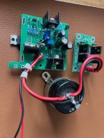
The casing is the heatsink so an aluminium casing is optimal. I combined it with Prasi LT4320 ideal rectifier for lower losses/less heat and a 15,000 µF 35V filter cap. Had my fun, it can go.. It was pretty expensive to build (both boards) so as usual I tried with success to forget the high costs. I think 100 Euro ex shipping within EU is acceptable but let me know if you think otherwise. I removed the standoffs as I used odd non standard americano stuff. The screws are usually OK contrary to the devices 🙂 M3 hardware is of course to be used.
The sawdust is to be removed by you ! Will include a TO220 insulation pad.
@codyt
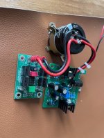
On the second look I've noticed connection points marked as R21-G. 😳 Several coffees do wonders.
I suppose that are connection points for R21 module reference ground wires?
In that case, for the second R21 supply that has role as the negative supply, reference ground wire has to be connected to the actual ground of that module, which is on your schematic marked as V-.

Attachments
Last edited: