Hi,
I have a couple of questions about my Croft super micro. I tried to create a schematic:

It looks similar to the schematics by @Alex M (see here) and also to this one. Please point me to errors in the schematic. There are differences in values (as always with Croft). For example I have 1K8 at R2 and 2K7 at R8 in both channels: the other schematics have 2K7 everywhere. This schematic shows the voltages on top of those resistors: I guess it has to do with the different voltages that sink current through the resistors?
EDIT: schematic updated
I have a couple of questions about my Croft super micro. I tried to create a schematic:
It looks similar to the schematics by @Alex M (see here) and also to this one. Please point me to errors in the schematic. There are differences in values (as always with Croft). For example I have 1K8 at R2 and 2K7 at R8 in both channels: the other schematics have 2K7 everywhere. This schematic shows the voltages on top of those resistors: I guess it has to do with the different voltages that sink current through the resistors?
EDIT: schematic updated
Attachments
Last edited:
Three remarks about the power supply:
1) The value of R21 is 390 Ohm in the schematic. That cannot be right. The value should be much higher.
2) Datasheets for the ECL85 give different values for the maximum cathode to heater voltage (Philips and Mazda-Belvu = 100 V; La Radiotechnique = 200 V; RCA = 220V). In the schematic the heater supply of the ECL85 is grounded. If really grounded, there would be 270 V between the heater and the cathode of the pentode section.
3) The voltage rating of the two 250 uF capacitors is 385 V. That value is too low for my taste. Before the ECL85 has warmed up and starts to pass current, the voltage over these two capacitors will likely be a bit higher than 385 V.
Just curious about your design decisions. For the line level inputs, the preamp has about a 1dB loss at full "volume". At 50% volume it has about 21 dB of loss. Was this intentional? Do you have another preamp for gain recovery in the chain or a very sensitive amplifier? Just trying to put the unit in context of how it would be used.
Yes, you are right: it has a bit low gain, can I adjust it by lowering R17...?
Many thanks, I updated the schematic: 1) I forgot to put the "K", of course it's a 390K not a 390R resistor. 2) My mistake: the transformer has no center tap, I corrected it. 3) The caps that are originally fitted are 385V, I would in any case recap with higher voltage rating - but altered the schematic to say 400V.
Three remarks about the power supply:
1) The value of R21 is 390 Ohm in the schematic. That cannot be right. The value should be much higher.
2) Datasheets for the ECL85 give different values for the maximum cathode to heater voltage (Philips and Mazda-Belvu = 100 V; La Radiotechnique = 200 V; RCA = 220V). In the schematic the heater supply of the ECL85 is grounded. If really grounded, there would be 270 V between the heater and the cathode of the pentode section.
3) The voltage rating of the two 250 uF capacitors is 385 V. That value is too low for my taste. Before the ECL85 has warmed up and starts to pass current, the voltage over these two capacitors will likely be a bit higher than 385 V.
Many thanks, I updated the schematic: 1) I forgot to put the "K", of course it's a 390K not a 390R resistor. 2) My mistake: the transformer has no center tap, I corrected it. 3) The caps that are originally fitted are 385V, I would in any case recap with higher voltage rating - but altered the schematic to say 400V.
No. The cathode follower will always have a gain of less than 1 (0dB). The only way to recover gain is with a dedicated gain stage.... can I adjust it by lowering R17...?
Usually when employing a volume control in a preamp, the end to end gain of the entire signal chain (for line level inputs) is set to around 20dB. Standard audio taper potentiometers are about a 20 dB loss at the 50% rotation (i.e. 12 o-clock) point. This means that with a line level input, and the volume control set half way, you get the same level output. Then you can adjust the signal up or down depending on your needs.
As it stands, you preamp is a net signal loss of somewhere between -1dB and -40dB depending on the volume control setting.
Another questions is about the line stage because I don't have this little circuit below the tube in the line stage:
View attachment 1447921
Would adding this circuit make a worthy improvement to the preamp? And if so: do I have to change some values in that circuit to adapt it to the higher input voltage of 300VAC from my transformer vs. the 240VAC shown in the above diagram, or can I use it as it is?
That is a regulated negative supply for the cathode of the valve. I'm not sure what improvement it would offer for a cathode follower like this though - possibly increasing the voltage swing? In a common-cathode voltage amplification stage it can be used to allow a larger cathode resistor and so reduce the voltage gain. I think a current sink on the cathode here would give a bigger improvement.
That is what Glenn told me. It seems that the 12BH7 is similar to a 6SN7, but pin compatible with the ECC82. The only caveat is that its heater draws more current.
Alex
About the phono preamp:
The RIAA correction takes place around the second triode section of the ECC83 by means of feedback from plate to grid. For this set-up you need this stage to have high gain.
But the plate resistance for ac-signal of this triode section is 270K in parallel with the 100K volume potmeter, making it only 73K. With this value the gain will not be very high (based on tables in Philips datasheets for the ECC83 I estimate a little less than 50, so a little than 34 dB).
For now, I assume that the designer calculated the values of the RIAA feedback network based on this value of 73K (I lack the knowledge to calculate this myself).
But when a tape recorder would be connected to "tape out", the plate resistance for ac-signal would get substantially lower than 73K, causing the gain of the second triode section of the ECC83 to get lower. I would think that this creates a situation in which the RIAA correction does not work proper anymore.
I am servicing another preamp for a friend of mine, it's a micro II special and has a slightly different schematic:

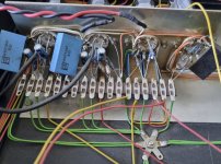
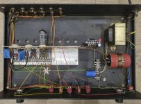
There is a neon bulb instead of the gas discharge tube, like mentioned also here. The regulator circuit is completely off, so I took out the resistors and measured them:

The picture above shows the neon bulb and 2 resistors that measure strange: the upper one looks like it should be a 270K (R24) but it measures 310K. The lower one (R22) could be a 81K (or 91K?) but measures infinity. I replaced the resistors and tried to make the regulator work. The bulb glows but the voltage at the output of the regulator is the same as at the input of the regulator. The bulb gives a voltage between 65 and 110V depending on the resistor values. I also tried to simulate it in LTspice but couldn't get any meaningful results.
I would prefer to rebuild the regulator, but it seems I can't get it to work, so I am tempted to just replace it with the maida regulator like the one that is used in my integrated phono amp:

Please help if you have any hints for me!
There is a neon bulb instead of the gas discharge tube, like mentioned also here. The regulator circuit is completely off, so I took out the resistors and measured them:
The picture above shows the neon bulb and 2 resistors that measure strange: the upper one looks like it should be a 270K (R24) but it measures 310K. The lower one (R22) could be a 81K (or 91K?) but measures infinity. I replaced the resistors and tried to make the regulator work. The bulb glows but the voltage at the output of the regulator is the same as at the input of the regulator. The bulb gives a voltage between 65 and 110V depending on the resistor values. I also tried to simulate it in LTspice but couldn't get any meaningful results.
I would prefer to rebuild the regulator, but it seems I can't get it to work, so I am tempted to just replace it with the maida regulator like the one that is used in my integrated phono amp:
Please help if you have any hints for me!
Attachments

Attachments
Found pictures online of a 25R with low gain mod, looks exactly like the tape out buffer circuit shown here:

Modded my super micro to match this circuit, but kept 4K7 as cathode resistor. The micro II special got the 500R for lower gain (soldered 560R across the existing 4K7). Both preamps sound very good now.
I think I am done with this little project. Thanks for the input!
Modded my super micro to match this circuit, but kept 4K7 as cathode resistor. The micro II special got the 500R for lower gain (soldered 560R across the existing 4K7). Both preamps sound very good now.
I think I am done with this little project. Thanks for the input!
- Home
- Amplifiers
- Tubes / Valves
- My Croft super micro schematic