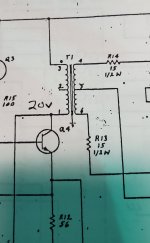
By convention the dot end is positive (in-phase) with other windings marked the same.
Without the rest of the circuit, we don't know whether the secondary phase is important.
Without the rest of the circuit, we don't know whether the secondary phase is important.
Could the dot just be a blemish, like other ones on the drawing? Normally, each winding would have a dot to assist in proper polarity (in/out of phase) hook up.
Looks like a "real" dot to me. But usually the secondary also has a dot.
Wouldn't be the first problem with documentation, though.
Wouldn't be the first problem with documentation, though.
A single dot is of no use - its a notation to show relative phase of windings, so all windings should be marked. However there is also the convention that all windings face the same direction, so dots are not normally needed. One dot is just wrong and raises questions more than it answers them!

Exactly what I was thinking. If the dot convention intent is to show phasing relation, relationship to nothing 😁
I seem to recall seeing small transformers, such as interstage or RF transformers, marked with a paint dot on the bobbin. Could it be that the dot marks pin 3? That'd be a bit odd, but not the first time odd markings were done on electronic parts.
Tom
Tom
- Home
- Source & Line
- Analog Line Level
- Dot convention, one dot