And in the shop today is another NAD favorite. T753 phase 1 receiver. Relays are not engaging on amplifier boards.
I wasn't getting power to the main voltage loop initially (power supply secondary board with output caps) due to a fried jumper from an actual bug!
Power supply board is fixed now as I'm getting ac output.
Now, the relay b pin has a small voltage change (2v-ish) and no change in relay A pin when powering on. I noticed that the 22v rail is not showing anything, but I have voltage to the 17.6v from the psu board.
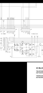
So all I am seeing is 17.6v AC through a single diode (d701 on main board) I'm just trying to understand how this works. I know a bridge rectifier would convert ac to DC, but a single diode would only give the positive half of the wave yes? Is the 12v regulator affecting this as well? How is this converting 17.6 ac to 22 dc? I've yet to test the diode and regulator to figure out why I'm getting no 22 voltage, or what else could be causing this.
I wasn't getting power to the main voltage loop initially (power supply secondary board with output caps) due to a fried jumper from an actual bug!
Power supply board is fixed now as I'm getting ac output.
Now, the relay b pin has a small voltage change (2v-ish) and no change in relay A pin when powering on. I noticed that the 22v rail is not showing anything, but I have voltage to the 17.6v from the psu board.
So all I am seeing is 17.6v AC through a single diode (d701 on main board) I'm just trying to understand how this works. I know a bridge rectifier would convert ac to DC, but a single diode would only give the positive half of the wave yes? Is the 12v regulator affecting this as well? How is this converting 17.6 ac to 22 dc? I've yet to test the diode and regulator to figure out why I'm getting no 22 voltage, or what else could be causing this.
Attachments
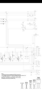
That's a Zener diode, connected in series after rectification and filtering to DC.
It drops some DC voltage, mainly to keep the regulator from getting too hot.
What are the DC voltages at the regulator pins?
It drops some DC voltage, mainly to keep the regulator from getting too hot.
What are the DC voltages at the regulator pins?
Which? D701 is rectifying diode, u702 is a voltage regulator so I'm assuming d716 is what you're on about. How would that affect the 22v rail?
Likely there is a circuit fault drawing excess current, causing the reg to fold back and drop its output DC voltage.
So if I test the zener and find negative voltage on the anode as there should be in this case, I should check the output side of the reg? Until now I've just been tracing the power from point A (T) to the relay circuit to see if there was a break or faulty component. If there is excess current draw from somewhere outside that path I'm unsure how to go about tracking that unless it's as straightforward as tracing that back in reverse from the reg output?
Updated, looks like the d701 diode was covered with hot glue from the ground jumper wire, it must have somehow gotten conductive over time because after I removed it to test the diode, it fired up and I have 22v now, front amp relay engaged. Unfortunately I now have a similar muting problem to my last project with my t751. All channels seem muted. So time to start probing that circuit.
- Home
- Amplifiers
- Solid State
- NAD T753 phase1 relay power issue.