Hello guys
Me preamplifier has 12au7 x1 and 12at7 x1 per channel. I think that its an mu stage cathode follower at least is what the manufacturer states. I will post a pic here of the one Chanel pcb ( the preamplifier now is has been rebuilded with point to point method exactly as it was with the pcb i mean with the same schematic) for someone here with more technical knowledge explaining to me this.
The tubes are double triodes. We have 2 cathodes 2 grids and 2 anodes per tube.
At the pcb you can see clearly that they put jumpers from cathode 1 to cathode 2 from grid 1 to grid 2 and from anode 1 to anode 2 per tube. Essentially they have merge the 2 triodes per tube. Is this something common?
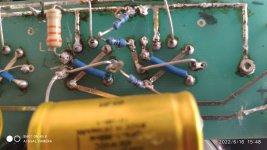
All the schematics i have ever seen in the tube double triode part they all have 3 points cathode grid and anode and then all the wiring connections. In the pic you can see the 12at7 in the left and the 12au7 in right. Ingore the third half tube in left . Its the other channel 12au7
How can i represent this in a schematic?
Me preamplifier has 12au7 x1 and 12at7 x1 per channel. I think that its an mu stage cathode follower at least is what the manufacturer states. I will post a pic here of the one Chanel pcb ( the preamplifier now is has been rebuilded with point to point method exactly as it was with the pcb i mean with the same schematic) for someone here with more technical knowledge explaining to me this.
The tubes are double triodes. We have 2 cathodes 2 grids and 2 anodes per tube.
At the pcb you can see clearly that they put jumpers from cathode 1 to cathode 2 from grid 1 to grid 2 and from anode 1 to anode 2 per tube. Essentially they have merge the 2 triodes per tube. Is this something common?
All the schematics i have ever seen in the tube double triode part they all have 3 points cathode grid and anode and then all the wiring connections. In the pic you can see the 12at7 in the left and the 12au7 in right. Ingore the third half tube in left . Its the other channel 12au7
How can i represent this in a schematic?
Attachments
Simple, just make the schematic connections with lines.
The schematic only has node connection information, not the physical embodiment of the circuit.
connect pin 1 to pin 6
connect pin 2 to pin 7
connect pin 3 to pin 8
The schematic only has node connection information, not the physical embodiment of the circuit.
connect pin 1 to pin 6
connect pin 2 to pin 7
connect pin 3 to pin 8
Manufacturer and model number please.I think that its an mu stage cathode follower at least is what the manufacturer states.
jeff

Hello guys again
Here are some more details for this board.
Its from the korato kvp20 preamp. The input singal is on the 12au7 right tube, the output is on the 12a7t left tube.
The b+ is connected only at the anode of 12at7. The filaments are on both 12v dc series as hooman correctly said. Thats why we haven't pin 9.
Can someone please tell me why they merge the triodes. Is this something common with these double triodes tubes?
rayma all the schematics i have seen have only 3 points in tubes diagram none of them referenced that type of connections and none of them showing somehow the merging triodes in the tube diagram on the schematics.
hooman the resistor you draw red is the bypass cathode resistor which is missing from the pcb with the bypass cathode capacitor parallel which is also missing. The 2 resistors you see next to your drawing are the 12au7 input singal connection. One resistor goes to grid of 12au7 and the other 1Mohm goes to ground
The 3 resistors that you circled are as they are from the factory.
Last edited:
- Home
- Amplifiers
- Tubes / Valves
- Question about my 12AU7 12AT7 preamp