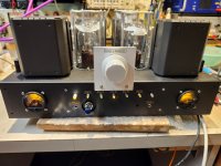
Hi. Just completed my first DHT Tube Preamp, based on the Allnic L-8000DHT, with my own bits and pieces. It is dual mono, with tube HV regulator with CLC pre-filter, dedicated low noise IC regulated supplies for each DHT tube heaters, original Allnic volume control I was fortunate enough to get from the web, Lundhall Power transformers, and Monolith Magnetics custom output transformers with amorphous core...
Landfall custom enclosure, awaiting a custom front plate from Hifi2000 in a few months. Neutrik and Cardas connectors, Furutech AC inlet, quality copper internal wirings, Mogami shielded signal wire, separated, one per channel, etc... The HV CLC inductor is an original Allnic transformer from unknown source I bought on ebay, maybe an interstage transformer I don’t know. I used the primary as an inductor, was close to the needed value, not perfect, but cheap at 20$ each, and matches nicely the chassis.
The preamp is two stages using DHT NOS tubes by STC, 3A/110A and 109B. These tubes used difficult to source old connectors. I got the 109B sockets from ebay, but I had to buy Yamamoto teflon machined socket from Japan for the 110A. It was expensive at 175$ for the pair…
I designed and made my own tube chimney inspired by the ones on the original Allnic. They are made using round standoff, diy machined top rings made by me, and cut to length acrylic tubing, all from Aliexpress. It is quite nice I must say. The microphonic STC preamp tubes are held in place by DIY teflon vibration absorption rings, again similar to the ones used by Allnic.
AC inlet, main power switch and fuse are on the back, not on the side as the original, location that I don’t like. It just fits on the rear panel. Doesn’t cause any line ac noise on the adjacent input pcb, so not that critical to have it located on the front side panel. I used a shielded internal AC cable with chassis drain wire just in case…
The preamp is perfectly silent, no noise, nothing. Gain of about 12.5X (21.5dB), bandwidth 71Khz, and nice square response and very now frequency response thanks to the very nice Monolith transformers (very expensive but worth every penny!).
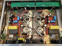
I did all the pcb and mechanical design, two months work. The preamp is mostly assembled point to point, mirror image around the central star ground copper solid core wire. The ground is connected to the chassis just at one location, near the chassis front. Power AC is connected to the chassis ground using a ground lift (two diode back to back) at the input EMI filter. The Audio ground is connected at strategic point on a central Star Gnd bar. Small pcb I made with soldered tabs are used to mount the remaining parts on the chassis.
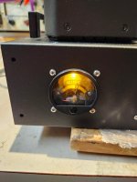
I even made my own Allnic style tube current meters, with led backlight...
This is the best preamp I ever heard in my system, period. One day I'll compare it with an original Allnic to see how the Monolith transformers compare to the Allnic ones. But that's for an other time.
One last project before I pack all my workshop and parts for possibly the next 6 months...
Landfall custom enclosure, awaiting a custom front plate from Hifi2000 in a few months. Neutrik and Cardas connectors, Furutech AC inlet, quality copper internal wirings, Mogami shielded signal wire, separated, one per channel, etc... The HV CLC inductor is an original Allnic transformer from unknown source I bought on ebay, maybe an interstage transformer I don’t know. I used the primary as an inductor, was close to the needed value, not perfect, but cheap at 20$ each, and matches nicely the chassis.
The preamp is two stages using DHT NOS tubes by STC, 3A/110A and 109B. These tubes used difficult to source old connectors. I got the 109B sockets from ebay, but I had to buy Yamamoto teflon machined socket from Japan for the 110A. It was expensive at 175$ for the pair…
I designed and made my own tube chimney inspired by the ones on the original Allnic. They are made using round standoff, diy machined top rings made by me, and cut to length acrylic tubing, all from Aliexpress. It is quite nice I must say. The microphonic STC preamp tubes are held in place by DIY teflon vibration absorption rings, again similar to the ones used by Allnic.
AC inlet, main power switch and fuse are on the back, not on the side as the original, location that I don’t like. It just fits on the rear panel. Doesn’t cause any line ac noise on the adjacent input pcb, so not that critical to have it located on the front side panel. I used a shielded internal AC cable with chassis drain wire just in case…
The preamp is perfectly silent, no noise, nothing. Gain of about 12.5X (21.5dB), bandwidth 71Khz, and nice square response and very now frequency response thanks to the very nice Monolith transformers (very expensive but worth every penny!).
I did all the pcb and mechanical design, two months work. The preamp is mostly assembled point to point, mirror image around the central star ground copper solid core wire. The ground is connected to the chassis just at one location, near the chassis front. Power AC is connected to the chassis ground using a ground lift (two diode back to back) at the input EMI filter. The Audio ground is connected at strategic point on a central Star Gnd bar. Small pcb I made with soldered tabs are used to mount the remaining parts on the chassis.
I even made my own Allnic style tube current meters, with led backlight...
This is the best preamp I ever heard in my system, period. One day I'll compare it with an original Allnic to see how the Monolith transformers compare to the Allnic ones. But that's for an other time.
One last project before I pack all my workshop and parts for possibly the next 6 months...
Attachments
Last edited:

Very nice build and attention to detail that is rewarded by the performance! Congratulations! 
Cheers,
Stephen
Cheers,
Stephen
Hi, sorry won’t show the schematics, too close to the original, still a commercial product. It is very simple, two stages preamp, simple cathode resistor bias, bypassed with an electrolytic cap, cap coupled to the second stage, same bias, anode transfo output. That’s it. Input is not balanced, only single ended. The balanced input pin 3(-) is simply terminated into a resistor. Output is pure balanced because of the output transfo. Biggest impact on sound quality are the tube choice naturally, the interstage coupling cap, and the output transformer, Allnic all nickel transfo on the original, Monolith Magnetics in my case (1k$ for the pair!)
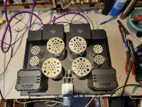
All DHT tubes heaters have separate power transformer secondaries, then a simple bridge rectifier, 10,000uf cap, a LDO 4V regulator, small output cap, that’s it. Very low noise DC heater supply, simple, elegant, nothing fancy. The power transformer is a very good quality Lundhall power transformer, it has two HV secondaries, and 4 heaters ones. I needed 6 heater voltages, so I bought an extra small Hammond transformer with two 6V secondaries for the two extra one, was fine because these two are supplying the DHT 4V regulators. I mount the Hammond transformer into a matching Lundhall enclosure, so the preamp looks symetrical.
Dual mono HV supplies, simple, cheap, small bridge rectifier, CLC filter, tube regulated voltage regulator, 7233 power triode pass element, small 5654 penthode tube used as an op-amp, a simple voltage divider to sample the output voltage on one input, simple zener voltage reference on the other hand. Countless diagrams of this type of tube regulator exist on the web. Here again nothing fancy for the parts, power MOX resistors, simple electrolytic, but large output 40uf film cap, in my case a 30uf Vishay cap with a IC 10uf. That’s all…
So to resume, very low noise, regulated HV and heaters supplies, very simple two stages preamp, good quality output transformer. I can probably improve the preamp by upgrading the preamp interstage coupling cap with a good Jupiter or even Duelund film capacitor. Rest of the parts are not fancy, simple MOX and electrolytic caps…
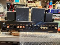
I did my own front controller board, all discrete, no processor digital noise, no remote. Power-on with a relay controlled by a simple push button switch, source selection by rotary switch, two poles, one for the input led, the other for the source selection relay. Rotary switch is Make-Before-Brake type, so no switching noise when changing the input. Mute starting timer that drives the input pcb mute relays, open the drive mosfet line and you then control the on/off mute after start up. A simple control 12V local supply, gnd is not connected to the preamp chassis or audio gnd. Output by a 10 lines flat ribbon cable that goes to the rear I/O pcb. 12V drives also the meter led back light. Simple, straight forward control, nothing fancy.
Rear I/O PCB are dual mono, mirror image, one relay per input, one mute relay and one output phase relays per pcb. Control signal goes between each board with simple jumper wires. As mentioned the balanced input are pseudo balanced, really just SE input, so no complex SE/BAL management by complex relays either. Output is balanced directly from the output relay. The SE output is simply done by a simple DPDT toggle switch on the back that short one side of the output transfo to gnd in SE mode. Again very simple, straight forward.
Front current meter is simply a voltmeter that measures the CLC inductor current drop voltage, so proportional to the preamp tube current supply.
SB
All DHT tubes heaters have separate power transformer secondaries, then a simple bridge rectifier, 10,000uf cap, a LDO 4V regulator, small output cap, that’s it. Very low noise DC heater supply, simple, elegant, nothing fancy. The power transformer is a very good quality Lundhall power transformer, it has two HV secondaries, and 4 heaters ones. I needed 6 heater voltages, so I bought an extra small Hammond transformer with two 6V secondaries for the two extra one, was fine because these two are supplying the DHT 4V regulators. I mount the Hammond transformer into a matching Lundhall enclosure, so the preamp looks symetrical.
Dual mono HV supplies, simple, cheap, small bridge rectifier, CLC filter, tube regulated voltage regulator, 7233 power triode pass element, small 5654 penthode tube used as an op-amp, a simple voltage divider to sample the output voltage on one input, simple zener voltage reference on the other hand. Countless diagrams of this type of tube regulator exist on the web. Here again nothing fancy for the parts, power MOX resistors, simple electrolytic, but large output 40uf film cap, in my case a 30uf Vishay cap with a IC 10uf. That’s all…
So to resume, very low noise, regulated HV and heaters supplies, very simple two stages preamp, good quality output transformer. I can probably improve the preamp by upgrading the preamp interstage coupling cap with a good Jupiter or even Duelund film capacitor. Rest of the parts are not fancy, simple MOX and electrolytic caps…
I did my own front controller board, all discrete, no processor digital noise, no remote. Power-on with a relay controlled by a simple push button switch, source selection by rotary switch, two poles, one for the input led, the other for the source selection relay. Rotary switch is Make-Before-Brake type, so no switching noise when changing the input. Mute starting timer that drives the input pcb mute relays, open the drive mosfet line and you then control the on/off mute after start up. A simple control 12V local supply, gnd is not connected to the preamp chassis or audio gnd. Output by a 10 lines flat ribbon cable that goes to the rear I/O pcb. 12V drives also the meter led back light. Simple, straight forward control, nothing fancy.
Rear I/O PCB are dual mono, mirror image, one relay per input, one mute relay and one output phase relays per pcb. Control signal goes between each board with simple jumper wires. As mentioned the balanced input are pseudo balanced, really just SE input, so no complex SE/BAL management by complex relays either. Output is balanced directly from the output relay. The SE output is simply done by a simple DPDT toggle switch on the back that short one side of the output transfo to gnd in SE mode. Again very simple, straight forward.
Front current meter is simply a voltmeter that measures the CLC inductor current drop voltage, so proportional to the preamp tube current supply.
SB
Last edited:
Low noise is nice -- but the filaments don't want voltage regulated DC. Since the two ends of the filament are at different potential, the grid-cathode and anode-cathode voltages seen at the two ends of the filament will be different (cathode=filament!), and so a music signal will want to develop across the filament pins. The voltage regulator will work against this music signal in order to achieve constant DC across the filament.All DHT tubes heaters have separate power transformer secondaries, then a simple bridge rectifier, 10,000uf cap, a LDO 4V regulator, small output cap, that’s it. Very low noise DC heater supply, simple, elegant, nothing fancy.
A better way is to use current regulated DC. This will not interfere with the music signal across the filament. Take a look at the Coleman regulator, which will nicely solve the problem.
Worked fine for Allnic on their DHT preamp, heaters are splited with two resistors, both bypassed by electolytic caps, guess that reduce greatly the music modulation effect ont eh DHT. There is always a few ways to do things, not here to argue endlessly. An other reason not to share schematics. I know this circuit makes very nice music, a very good start and that’t what important. It is done know and I won’t touch it again, time to pack, thanks anyway.
SB
SB
Of course regulated DC works. However, a Coleman style DC supply would work better.Worked fine for Allnic
HiThe preamp is two stages using DHT NOS tubes by STC, 3A/110A and 109B.
Is it 3A/110A first amplification stage followed by 3A/109B second amplification stage?
109B is 3A/109B?
Thanks
🙂
- Home
- Amplifiers
- Tubes / Valves
- My First DHT tube Preamp, and probably my best