Ok guys i am in complete loosing my mind here.
I have 2 identical toroidal transformers of my tube pre for b+. They output 230 v ac 120 mA exactly the same for both measured. 4 diodes in4007 in both transformers and now begins the craziness. On the diode's outputs One outputs 315v dc and the other 215v dc. i have change 65467765433567787654478 diodes no luck always the same scenario as above.
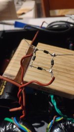
I forgot to tell you that the transformer that outputs 315v dc the diodes are normally on the psu circuit and the other transformer that outputs 215 is alone in the air with the diodes only.
I mesure for both transformers only the diodes output.
I have 2 identical toroidal transformers of my tube pre for b+. They output 230 v ac 120 mA exactly the same for both measured. 4 diodes in4007 in both transformers and now begins the craziness. On the diode's outputs One outputs 315v dc and the other 215v dc. i have change 65467765433567787654478 diodes no luck always the same scenario as above.
I forgot to tell you that the transformer that outputs 315v dc the diodes are normally on the psu circuit and the other transformer that outputs 215 is alone in the air with the diodes only.
I mesure for both transformers only the diodes output.
Last edited:
If I'm reading your problem correctly, you have one toroid in a functioning power supply, presumably with a capacitor-input supply. The other is floating free with only diodes connected. I could be wrong, but with no filter capacitor added to the diodes, you will not get the voltage you are looking for. In fact it will be less than 1x the secondary voltage of the transformer. To get the 315VDC you have to add a cap after the diodes.

Maybe the circuit with 315V output is connected to a filter cap and the other not.
Edit: Missed post above.
Edit: Missed post above.
Ok guys maybe i have found the cause.
In the first place i extract the diodes from the circuit to identify why i had 100v in the plates of the left channel and not 217v dc as the normal right channel. Then i measured the voltage out of the circuit 215v. Then after your posts i add an electrolytic cap 100mf 400v and boom 315v on the multi meter. That tells me that the caps janzten cross cap 100mf 400v with a jantzen superior cap 0.22 mf 1200v as bypass in the left channel circuit are going bad or there is a missing trace somewhere . The caps are new only 10 hours run time. I DONT BELIEVE IT.
Is it possible to check the jantzen caps with a multimeter to see if its bad or not?
Last edited:
Charge the cap from a power supply at a safe level of between 10V to 25V, through a 10k resistor.
The voltage on the cap should build up from 0V to full voltage over about 5 seconds if it's 100uF.
This assumes the meter input resistance is much higher than 10k.
The voltage on the cap should build up from 0V to full voltage over about 5 seconds if it's 100uF.
This assumes the meter input resistance is much higher than 10k.
MKP crossover caps are intended to handle at least an amp or two of continuous AC current. Levels that midranges and tweeters can take. 8 watts average power is 1 amp. A couple hundred mA tube amplifier power supply poses no challenge. As an output or coupling cap on a 3 kVA inverter or SMPS they might cook.
No problem for a PT. No current - no heating....not good for the transformer.
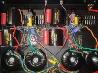
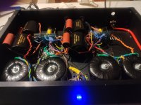
Ok guys finaly i have found for good this time the cause. The real cause. So the pcb of the left chanel was shorted with the chassis because one trace was too close with the metal stand that holds the pcb. Thats why everything were working normaly at the air outside of the pcb. (The diodes that blow up in the air in the pic that i posted was already faulty from the pcb problem). I am so stupid that i left there the metal stands. I blow up about 34 diodes until found the problem. I was ready to throw it from the balcony. I have cut the metal stand 2 mm away from the trace. Its 5 o'clock in the morning here in Greece and i am sitting here and watching it operate now like swiss clock. I have exactly the same voltages on both channels now. 220v dc b+ x 2 exactly and 12.01v dc Filaments x 2 exactly both PSU's. But i don't want to connect it to the preamplifier yet.. i am afraid. The good thing is that about an hour now there is no smoke. Thank you guys for your help and your time. I will post a pic. Its not as i wanted to look like its a little messy but..... I am not seriously put my hands and iron solder again inside. I have psychological issue now that everything will be going wrong again and i will have smoke again.
Attachments
Last edited:
Fire up the power supply on a dim bulb, with the tubes pulled. Then discharge the caps (safely). Make sure there is no drama there, then proceed.
Last edited:
Yes, it only means you need to have better building practices.
I recently built my amp and thought one tube was bad, or that the bias had broken a capacitor etc. All it was were two wires very close so that it would just take a small vibration to make an intermittent contact and send the amp into noise for a second.
I recently built my amp and thought one tube was bad, or that the bias had broken a capacitor etc. All it was were two wires very close so that it would just take a small vibration to make an intermittent contact and send the amp into noise for a second.
That's a lotta diodes!Ok guys i am in complete loosing my mind here.
I have 2 identical toroidal transformers of my tube pre for b+. They output 230 v ac 120 mA exactly the same for both measured. 4 diodes in4007 in both transformers and now begins the craziness. On the diode's outputs One outputs 315v dc and the other 215v dc. i have change 65467765433567787654478 diodes no luck always the same scenario as above.
I forgot to tell you that the transformer that outputs 315v dc the diodes are normally on the psu circuit and the other transformer that outputs 215 is alone in the air with the diodes only.
I mesure for both transformers only the diodes output.
Hello guys
My tube preamplifier PSU is up and running until now flawless and the difference with the updates/upgrades is night and day regarding the SQ. The uf 4007 diodes replacing the in4007 made a significant difference and also the bypass caps in the b+ section. So in my previous post i wrote that i have found the cause of my big frustration of blow up 36 diodes in the process of upgrading. But .....
After an investigation further i realised that the cause of shortcircut of metalic stands that holds the pcbs to the chassis vertical was contacting with a pcb positive trace leads to blow 34 diodes i am not so sure that indeed was the real cause.
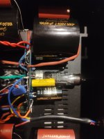
I explain. The pcb was indeed placed with the stands screw to the chassis but all the cable regarding ground was off the pcb. I mean that the actual pcb ground was floating to nowhere. So if the positive trace contacting with the metal stand and with the chassis there is no short circuit. Right? The only negative contact with the chassis is the transformer ac input yellow cable . Is this enough to make a short circuit? I ask this because if i haven't found yet the real cause then i have a serious problem . The only thing i remember is that after too many fail attempts to reassembly the parts and connections to the pcb only succeeded when i cut the metalic stands 2mm short way from this positive trace. This positive trace is the positive of the filter cap right after the diodes in the b+. And to help you understand more detailed the filaments section psu sitting on the same pcb was working flawless all the time and shares the ground with the b+
ONLY THE B+ Section was blowing the diodes.
Before i had made the exact same procedure with the right channel PSU and succeeded with the first try. But the metal stands there in the right channel psu pcb was all ready 3 mm away from any pcb trace.
I must find the real cause for good and i have to do it fast. Every time i power on the psu i cross my fingers.
And the sound is brilliant i dont believe it. How long will it last?
My tube preamplifier PSU is up and running until now flawless and the difference with the updates/upgrades is night and day regarding the SQ. The uf 4007 diodes replacing the in4007 made a significant difference and also the bypass caps in the b+ section. So in my previous post i wrote that i have found the cause of my big frustration of blow up 36 diodes in the process of upgrading. But .....
After an investigation further i realised that the cause of shortcircut of metalic stands that holds the pcbs to the chassis vertical was contacting with a pcb positive trace leads to blow 34 diodes i am not so sure that indeed was the real cause.
I explain. The pcb was indeed placed with the stands screw to the chassis but all the cable regarding ground was off the pcb. I mean that the actual pcb ground was floating to nowhere. So if the positive trace contacting with the metal stand and with the chassis there is no short circuit. Right? The only negative contact with the chassis is the transformer ac input yellow cable . Is this enough to make a short circuit? I ask this because if i haven't found yet the real cause then i have a serious problem . The only thing i remember is that after too many fail attempts to reassembly the parts and connections to the pcb only succeeded when i cut the metalic stands 2mm short way from this positive trace. This positive trace is the positive of the filter cap right after the diodes in the b+. And to help you understand more detailed the filaments section psu sitting on the same pcb was working flawless all the time and shares the ground with the b+
ONLY THE B+ Section was blowing the diodes.
Before i had made the exact same procedure with the right channel PSU and succeeded with the first try. But the metal stands there in the right channel psu pcb was all ready 3 mm away from any pcb trace.
I must find the real cause for good and i have to do it fast. Every time i power on the psu i cross my fingers.
And the sound is brilliant i dont believe it. How long will it last?
Last edited:
You will have to buy some current meters and measure all your return for current and slowly power this thing on with a variac.
A short with the power supply output and the ground (yellow) should be enough to blow the main input fuse or the B+ fuse.
If not the input fuse is too low, and it is a GOOD IDEA to install a B+ fuse usually 1.5x max ripple current is OK.
some 500ma I use when I power on new designs to protect the transformers and tubes and parts.
then I place 1.5 A , then I place the final fuse which can be 2A or 3A.
I use at least 10mm standoffs to make sure that there is sufficient clearance between HV and chassis. If this is not an option trimming solder joints so that they are free of sharp points and covering the area with Kapton (polyimide) tape can be very helpful.
If this is just a clearance issue between a particular standoff and an HV circuit point on the board a nylon standoff will solve the problem.
If this is just a clearance issue between a particular standoff and an HV circuit point on the board a nylon standoff will solve the problem.
- Home
- Amplifiers
- Tubes / Valves
- I am loosing my mind here please help