Hello, I recently acquired a pair of these in great condition. They have a couple issues, but hopefully not a major problem.
I have the full build and owners manual along with schematics
1. The LED's that turn from red to green on the preamp board are out and will need to be replaced. The part number listed in the manual HZ-MNT LED with a 895000 designation. I am having trouble finding this at mouser with this number, although there is a 895006 that comes up as a led that hey stock.Any help sourcing these would be much appreciated
2. I have a minor hum coming from one of them I have not moved tubes around to see it they are causing it. This leads me to my next question. Does this need to be recapped? It was produced somewhere around 1995.
3. If there tubes in it are original, should I just buy new ones?
4. How can I ensure that there is no residual energy in the amplifer so that I can open them up and look around, I wants to listen to them, not have them take me out haha.
5. Thanks for any help along the way on these
Last edited:
I would plan on replacing all the electrolytics in the power supply. You could pull and test them first thou. Be sure to discharge them first. 🙂Does this need to be recapped? It was produced somewhere around 1995.
I would use the original tubes for the time being, unless it's obvious the EL34's are well used.If there tubes in it are original, should I just buy new ones?
Never have more than one hand in the amp if it's turned on. You don't want voltage going thru your chest. Always use a clip-on ground lead if you're going to poke around checking voltages. If you're going to work on the amp, discharge the main filter caps in the power supply first.How can I ensure that there is no residual energy in the amplifer so that I can open them up and look around, I wants to listen to them, not have them take me out haha.
Does the LED look like this:https://www.digikey.ca/en/products/detail/everlight-electronics-co-ltd/MV5437/2675600
Please post up a schematic if you're able. And pics of the amps too. 🙂
jeff
Last edited:
Check if you see a "thick" bleeder resistor accross (one of) the electrolytic capacitors.
This should unload the capacitors in less than a minute to be safe. Use a DMM to check for a remaining voltage.
Stay safe.
This should unload the capacitors in less than a minute to be safe. Use a DMM to check for a remaining voltage.
Stay safe.
It might not be the diode that is defunct, it might be wrong bias adjustment.
I would start measuring the voltages and compare with the schematic before any
replacements of components.
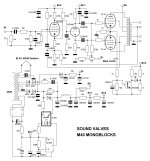
Attatching a schematic made by a diyaudio user
hifiengine claims they have the user manual
I would start measuring the voltages and compare with the schematic before any
replacements of components.
Attatching a schematic made by a diyaudio user
hifiengine claims they have the user manual
Attachments
Last edited:

+1I would start measuring the voltages and compare with the schematic before any
replacements of components.
Ok, got home from work today, moved tubes left to right. Played them for an hour or so pretty loud and they were well heated up. Due to the left right channel swap more than likely one was ~.9v one was ~1.1v. I dialed them in, and I still have the same light/diode issue. On one, the red light comes on while the amp is in soft mode, the other nothing, then the red goes off an sound comes up slowly but fully on both amps. So I think I do need those led's to be replaced.
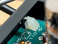
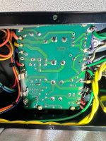
Noted above, I do not see a resistor strap from the bottom, so I do post this picture for two reasons, one to see if I am missing that, and two I want to make sure that the caps do not have any juice left in them. Can I just measure each one across the bottom of the board? And if there is some, what is the best way to easily discharge each one?
Also, all the other tiny caps that I can't see yet, do I need to discharge those as well before digging in a bit more?
Thanks!
Attachments
It's a fairly simple drive on the LED's. As you checked the voltage across the 10ohm resistor to be 1 Volt your bias
is correct.
As the circuit is simple i'd replace both the transistor and the LED and check the resistors around them for correct value.Also replace the 100uF cap as it might be damaged.
is correct.
As the circuit is simple i'd replace both the transistor and the LED and check the resistors around them for correct value.Also replace the 100uF cap as it might be damaged.
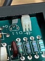
I put this down for a bit, but want to get parts ordered. I am still struggling to find the right LED. Any tips on that part exactly? Also the transistor in question is the 3 legged one in the picture, correct? Thanks!
Any input on determining the correct replacement LED? Thanks!It's a fairly simple drive on the LED's. As you checked the voltage across the 10ohm resistor to be 1 Volt your bias
is correct.
As the circuit is simple i'd replace both the transistor and the LED and check the resistors around them for correct value.Also replace the 100uF cap as it might be damaged.
The LED is not important, it's the transistor ( 2n5088) that is . When voltage on base exceeds the "knee" it will start
to conduct .
to conduct .
@ petertub SO I got around to ordering my capacitors and transistors. When doing so, I made a mistake and it followed me all the way through one of the 2 amps. I ordered 4x) 47uf, 25V axial caps, instead of 4x) 47uf, 100V. I was focused on R&R and polarity more than reading the cap values while working on it unfortunately. Once I double checked everything except values, I powered it up. It was fine until I saw a plume of smoke, and no new type of reaction with the LED's. Needless to say I powered it down, unplugged, and walked away very disappointed in myself. A couple days later, I was able to find some time to remove the power board again. I already knew that the power board fuse had blown during this episode. After unsoldering the power board for access, it was easy to see that one of these two 47uf, 25V caps partially exploded. I am now wondering how to pick up the pieces here. I am wondering how much collateral damage may have occurred. I am pissed at myself, but also eager to get through the project and see them working correctly when finished. Any help would be appreciated.
Which capacitors did you change ? The bias smoothing caps ?
Anyway replace them . As you shut it off there is likely no more damage done.
You can clean the board with isoprylalkohol or similar.
( and as it is a mistake to do several things at once when trying to solve a problem )
Relace the caps, remove power tubes and make sure you have a negative voltage in grid (pin 5) adjustable with the
bias adjustment pots. Then maximase the negative voltage, power off and install the power tubes. Power up
and measure with a voltmeter on the bias test point and adjust.
When this is done continue with the transistor/LED thing.
@petertub
Capacitors came in and have been installed. Again, they were on the power board. Would a 2 amp standard blow be good to test with, it's all I have short of stealing the other slow blow from the other monoblock. Trying to find a slow blow locally, but not having any luck, may have to just amazon them.
Capacitors came in and have been installed. Again, they were on the power board. Would a 2 amp standard blow be good to test with, it's all I have short of stealing the other slow blow from the other monoblock. Trying to find a slow blow locally, but not having any luck, may have to just amazon them.
Is the problem that one amp blows the fuse ? Then limit the current by ( bulb limiter or variac) , try to measure
voltages and identify what is drawing current. Removing all EL34 might be a good start.
Don't use a larger fuse !
voltages and identify what is drawing current. Removing all EL34 might be a good start.
Don't use a larger fuse !
Hey there, no the power board has a 2 amp slow blow on it that blew after that under voltage rating capacitor failed. I think that is the only problem, and those have been replaced with the correct voltage rated caps. So now, assuming nothing fried last time, they should be ready to fire up and work. I was mainly wondering if I could used a fast blow instead of a slow blow, as it was on hand. I am guessing that it's a slow blow so that it survives inrush current? Thanks
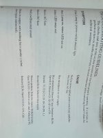
Ok, I got the other one reccaped and all went well, powered on and biased them both. Still having this issue of the status lights being off.
One amp goes to red, but never to green, the other, the LED lever come on at all. Is it possible that the leds are dead, this is my other list of possible causes, per the manual. @petertub
One amp goes to red, but never to green, the other, the LED lever come on at all. Is it possible that the leds are dead, this is my other list of possible causes, per the manual. @petertub
Attachments
- Home
- Amplifiers
- Tubes / Valves
- Sound Valves M40 Mono amplifiers (Dynaco ST70 circuit)