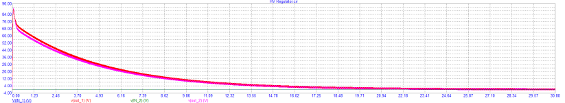
Hello. I'm simulating Frank's 6sn7 preamp and have a question about output 5uf capacitor. If I leave it with 5uf than the operation will stabilize around 30 sec (please consider red and purple waves in the plot) . If I use 0.047uf instead the amplifier will work from start. What's the use of such capacity?
Attachments
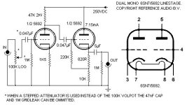
The pre-amp is designed to drive low impedance output loads. If you put in a small cap then the bass response will be limited. F = 1/(2*PI*R*C). Where R is your load and C the cap you have chosen. I agree that the use of a 1M output resistor is rather high. You could replace with 100k. Tubes take 30s to warm up anyway.

Rather then changing preamp, its easier to install 'delay on' on output.
Also when installing a "delay" you must take into design to silence the output at power off before the B+ begins to fall.
That might be a more difficult problem to solve then the easy one : use a proper dimensioned capacitor.
That might be a more difficult problem to solve then the easy one : use a proper dimensioned capacitor.
Power off muting can be made very fast with proper design, much quicker than the cooling off of the tubes.
I designed such a circuit back in 1990, for a commercial product.
I designed such a circuit back in 1990, for a commercial product.
It must be faster then the fall of B+ in order to avoid a huge pulse.Power off muting can be made very fast with proper design, much quicker than the cooling off of the tubes.
Proper size of cap would be something that cuts out less then 20hz ( or whatever speakers you have). In any case
there is no program material below 20hz only noice and rumble.
It is also simple to put a switch with 10-100 ohm resistor to ground as mute after the 5 uF
Leave on only in power on for seconds and put on just before power off
Walter
Leave on only in power on for seconds and put on just before power off
Walter
I mean F = 1/(2*PI*R*C). R=100k, F= 20 Hz, Then C = 80 nFIt must be faster then the fall of B+ in order to avoid a huge pulse.
Proper size of cap would be something that cuts out less then 20hz ( or whatever speakers you have). In any case
there is no program material below 20hz only noice and rumble.
Depends on you load. Could be a volume pot say 10k. If you make F=20Hz then that will attenuate your signal by 3dB which if your speakers are up to it noticeable. So worst case 10K load and f=8Hz, about 2.2uF. SO depending on your load 80nF, .8uF or 2u2 or even 5uF.
Personally, I don’t really concern myself with behavior during turn on unless it’s going to damage something or affect long term reliability. I only listen after everything has warmed up a bit and, as has been pointed out, tube gear doesn’t reach stable operating points immediately after turn on.Hello. I'm simulating Frank's 6sn7 preamp and have a question about output 5uf capacitor. If I leave it with 5uf than the operation will stabilize around 30 sec (please consider red and purple waves in the plot) . If I use 0.047uf instead the amplifier will work from start. What's the use of such capacity?
As for the parts values . . . The cap and resistor form a high pass filter. It’s common practice to set the -3db point at 2 hz (or thereabouts) so that any frequency from 20 Hz up is not affected by any possible phase issues.
There are any number of combinations of cap and resistor value that result in a -3db point of ~2 Hz. An online high pass calculator will show you this.
Using common parts values . . . If you use a 1 meg resistor then 0.1 uf will give you a rolloff at 1.59Hz. If you use a 100k resistor then a 1 uf cap will give you exactly the same rolloff point.
If you’re using expensive “boutique” caps one reason to use lower values is that they might be considerably less expensive. I’m sure there may be other considerations though. I’m not very technically oriented.
The rolloff point of the combination in the schematic (5uf, 1 meg)is ridiculously low at .03 Hz. Not sure why they would do that. Even 2 Hz might actually be lower than necessary if your speakers can’t reproduce 20Hz. Most can’t, especially smaller “bookshelf” types. Also, what is the frequency range of your ears? An online frequency generator will give you an idea of the practical limitations of the combination of your speakers and hearing.
As for the “thump” issue . . . . If you follow the proper order of turn on / turn off for your amp you won’t have any issue with thumps. The sequence for the amp is “on last” and “off first”. No additional circuitry is necessary if you do it like this.
Delay on, quick off is normal feature for any speaker protection circuits. It could work here as well.Also when installing a "delay" you must take into design to silence the output at power off before the B+ begins to fall.
That might be a more difficult problem to solve then the easy one : use a proper dimensioned capacitor.
Another thead in diyaudio recomnends Rod Elliots P33 project.
I prefer to have the protection at the source of the noise. It could damage some power amplifiers as well.
Please explain to me why an preamp should pass signals of a frequency that does not occur in the recorded media and where the speakers won't emit any music information. The only thing that occurs in the subzero range is rumble fromPersonally, I don’t really concern myself with behavior during turn on unless it’s going to damage something or affect long term reliability. I only listen after everything has warmed up a bit and, as has been pointed out, tube gear doesn’t reach stable operating points immediately after turn on.
As for the parts values . . . The cap and resistor form a high pass filter. It’s common practice to set the -3db point at 2 hz (or thereabouts) so that any frequency from 20 Hz up is not affected by any possible phase issues.
There are any number of combinations of cap and resistor value that result in a -3db point of ~2 Hz. An online high pass calculator will show you this.
Using common parts values . . . If you use a 1 meg resistor then 0.1 uf will give you a rolloff at 1.59Hz. If you use a 100k resistor then a 1 uf cap will give you exactly the same rolloff point.
If you’re using expensive “boutique” caps one reason to use lower values is that they might be considerably less expensive. I’m sure there may be other considerations though. I’m not very technically oriented.
The rolloff point of the combination in the schematic (5uf, 1 meg)is ridiculously low at .03 Hz. Not sure why they would do that. Even 2 Hz might actually be lower than necessary if your speakers can’t reproduce 20Hz. Most can’t, especially smaller “bookshelf” types. Also, what is the frequency range of your ears? An online frequency generator will give you an idea of the practical limitations of the combination of your speakers and hearing.
As for the “thump” issue . . . . If you follow the proper order of turn on / turn off for your amp you won’t have any issue with thumps. The sequence for the amp is “on last” and “off first”. No additional circuitry is necessary if you do it like this.
the record player and possibly tonearm resonances. All of this will only result in added doppler distortion.
If the poweramp is tubed with output transformers we know that it will not be reproduced correct but possibly
will amplitude modulate the music signal.
So why ?
- Home
- Amplifiers
- Tubes / Valves
- Frank's 6SN7 preamp output capacitor question