I have 8 other phono stages and the tonal balance of my Naim Stageline K is a bit on the bright side but it suits my Linn Troika or Karma cartridges quite well on a precirkus LP12. Balances out quite nicely and there is some synergy going on. It gives the music some nice drive and dynamics - with the PRAT philosophy.
However there is an obvious problem in a lack of low bass to my ears. I know Naim circuits are bandwidth limited to some extent in both the top end and low end but to me it sounds like everything below around 40 Hz is missing, compared to all the other phono stages I’ve got. I assume it must have quite a shallow high pass filter. It’s
The old Naim Phono preamps cards are apparently the same circuit as the Stageline, and I found a circuit diagram of here:
http://www.neilmcbride.co.uk/mcboard.pdf
Might it be possible to tweak the circuit component values to make it roll off a bit little lower in the bass? - not massively, just a bit.
If anyone has any ideas which components to target it would be appreciated?
I thought maybe the uF value of series input/output caps could be raised, but 10uF in each position seems more than enough.
If the excessive high pass/bass roll off is built within the RIAA section it might be more challenging to address. I don’t have simulating software like LTspice etc. You need to take into account the neg feedback loops etc.
I know the Naim purists probably won’t like this idea, but it’s a decent phono stage with the right kind of cartridge and turntable, - if the bass extension could be improved just a bit I’d be quite happy with it using the Troika/Karma.
I’m not using it with other Naim equipment.
It’s a bit of a long shot, but if anyone has any ideas it would be much appreciated!
Not at all a long shot. Increase C4 to around 220uF or 330uF.
If that doesn't help enough, also increase C1 to around 33uF.
It appears there is no bypassing on the rail, check and see.
If not, you might add a good quality 0.1uF to ground at the emitter of Q4.
If that doesn't help enough, also increase C1 to around 33uF.
It appears there is no bypassing on the rail, check and see.
If not, you might add a good quality 0.1uF to ground at the emitter of Q4.

Thanks a lot for the tips. I’ll
Change C4 as you suggest.
Much appreciated.
The 10uF C1 input cap is a tantalum but you can also get them in 33uF. I can order some. I do have a 33uF Non polar electrolytic I could use as a test. Is a bipolar/non polar cap ok to try?
Thanks for the tip re bypassing the rail. Excuse my ignorance but what would that do? I only have quite basic electronic knowledge!
For C1 use only a solid type tantalum capacitor, otherwise use a nonpolar electrolytic. I would use what you have.
The rail may be bypassed in your unit, check and see. It is normally necessary in most circuits, even with a regulator.
The rail may be bypassed in your unit, check and see. It is normally necessary in most circuits, even with a regulator.
The circuits are definitely different, for example the input transistor Q1 is actually made up of several paralleled transistors.
That circuit diagram is supposed to be an old NA323 MC preamp board. As far as I know all the Naim phono boards always used discrete transistors (although there were several versions, so maybe the earliest one didn’t)
Maybe the circuit diagram is simplified? Not totally sure though.
Maybe the circuit diagram is simplified? Not totally sure though.
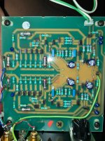
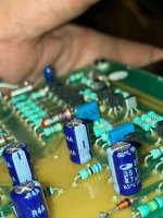
The C4 caps are defo 47uF (pic - the further away pair), so I’ll try increasing the value.
C1 caps are defo 10uF (pic) so I’ll try to increase those too.
I’ll try to identity if there are rail bypass caps. What’s the issue if there aren’t any?
C1 caps are defo 10uF (pic) so I’ll try to increase those too.
I’ll try to identity if there are rail bypass caps. What’s the issue if there aren’t any?
Attachments

The circuits are definitely different, for example the input transistor Q1 is actually made up of several paralleled transistors.
That's in the schematic as well as the photographs. Q1 and R5 in the schematic have a (x5) note next to them.
Increasing R14 and tweaking R17 to get the bias voltage at the collector of Q9 back to the old value might help increase bass, although it is weird that you need to modify anything in the first place.
Marcel thanks for pointing out the transistor X5 note in the circuit diagram. I had noticed it before actually but forgot! Makes sense now.
Thanks for the extra tip for increasing bass. I’ll bear it in mind and probably try it too.
I found a thread on another forum where someone ran RIAA sims. For the original 323 board it looks to be -3 dB down at 40 Hz and -4 dB down at 30 Hz. The Stageline is probably the same and I can really hear this roll off in the bass.
https://pinkfishmedia.net/forum/threads/naim-523-riaa-component-values.296725/#post-5411088
A possible reason for it is mentioned in a post above - to avoid rumble with older Idler decks that were notorious for rumble. Not sure how true that is though.
https://pinkfishmedia.net/forum/threads/naim-523-riaa-component-values.296725/#post-5407748
The OP has the 523 board but it’s the same circuit with a few different component values.
Last edited:
Sorry I misread. The OP on that thread didn’t have 523 boards but did an RIAA sim with its values.
On another note, regarding changing tbe C4 cap values from 47 to 220 or 330 uF, what kind of electrolytics are best for that position?. Would I get any benefit from more audio orientated caps like Elna Silmic or Panny FG? Or would a low ESR type cap be better?
C1 and C4 are coupling capacitors, Nichicon UES series (bipolar) at 35VDC would be good.
Thanks for that I’ll order some for C4.
Apparently if you change the tant caps for something else you loose some of the Naim sound, so I’ll probably order some 33uF tants for C1
Apparently if you change the tant caps for something else you loose some of the Naim sound, so I’ll probably order some 33uF tants for C1
Marcel thanks for pointing out the transistor X5 note in the circuit diagram. I had noticed it before actually but forgot! Makes sense now.
Thanks for the extra tip for increasing bass. I’ll bear it in mind and probably try it too.
I found a thread on another forum where someone ran RIAA sims. For the original 323 board it looks to be -3 dB down at 40 Hz and -4 dB down at 30 Hz. The Stageline is probably the same and I can really hear this roll off in the bass.
https://pinkfishmedia.net/forum/threads/naim-523-riaa-component-values.296725/#post-5411088
C4 causes first-order roll-off with a cut-off frequency of 15.39 Hz. At 30 Hz, it causes a drop to -1.015 dB and at 40 Hz, -0.6 dB.
The funny thing about R14 is that R14 is theoretically already 32.58 % too high, too high if the discrete amplifier Q6-Q7-Q8 had nullor (ideal op-amp) behaviour, that is. Apparently Naim has tweaked R14 to correct for finite loop gain, but not sufficiently.
If you want to try changing R14, I would do something like this:
Solder a resistor with a value in the 1 kohm to 10 kohm range to the emitter of Q8/collector of Q9, connect the other side of the resistor to the positive input of a multimeter, negative lead to ground. The resistor is just to make sure that the leads of the multimeter won't cause instability.
Measure the DC voltage.
Replace R14 with 100 kohm and R17 with 47 kohm in series with a 250 kohm trimmer potmeter.
Turn the trimmer potmeter until the DC voltage is back to its original value
Desolder the 47 kohm resistor and trimmer potmeter and measure their resistance.
Round it to the nearest E12 value and change R17 to that value.
Check that the DC voltage is about right and remove the 1 kohm...10 kohm resistor.
(I've left out the obvious steps of turning on the preamplifier to measure voltages and turning it off again to change things.)
Hi Marcel,
Thanks a lot for the info and those instructions.
As for C4, I guess all the main coupling caps and components in the RIAA section add up and have a cumulative effect, so if I can get back around 1dB at 30 dB from changing C4 that will probably help. I’ve ordered some 330uF 50V caps for the job.
Thanks for your other instructions. Excuse my ignorance with electronics but why does increasing R14 and tweaking R17 to get the bias voltage at the collector of
Q9 increase bass?
I will defo try your instructions if raising the values of C4 and C1 isn’t quite enough.
Last edited:
R14 is part of the RIAA correction network. The tweaking of R17 to get the bias voltage back to normal is only meant to prevent that changing R14 has side effects, such as reduced signal handling.
R22, R14 and C5 are part of the feedback network around the second stage. The higher the impedance of this branch, the less negative feedback and the more gain. When the frequency decreases, the impedance of C5 increases, which also makes the impedance of the whole network R22, R14 and C5 increase. When the frequency gets so low that the magnitude of the impedance of C5 becomes equal to R14, R14 starts to dominate over C5 and the impedance of the network R22, R14 and C5 becomes more or less constant. With a higher R14, this happens at a lower frequency, extending the bass boost of the RIAA correction network.
R22, R14 and C5 are part of the feedback network around the second stage. The higher the impedance of this branch, the less negative feedback and the more gain. When the frequency decreases, the impedance of C5 increases, which also makes the impedance of the whole network R22, R14 and C5 increase. When the frequency gets so low that the magnitude of the impedance of C5 becomes equal to R14, R14 starts to dominate over C5 and the impedance of the network R22, R14 and C5 becomes more or less constant. With a higher R14, this happens at a lower frequency, extending the bass boost of the RIAA correction network.
Hi Marcel. Sorry for the slight delay to reply. Thanks for the explanation. Been trying to understand what you said.R14 is part of the RIAA correction network. The tweaking of R17 to get the bias voltage back to normal is only meant to prevent that changing R14 has side effects, such as reduced signal handling.
R22, R14 and C5 are part of the feedback network around the second stage. The higher the impedance of this branch, the less negative feedback and the more gain. When the frequency decreases, the impedance of C5 increases, which also makes the impedance of the whole network R22, R14 and C5 increase. When the frequency gets so low that the magnitude of the impedance of C5 becomes equal to R14, R14 starts to dominate over C5 and the impedance of the network R22, R14 and C5 becomes more or less constant. With a higher R14, this happens at a lower frequency, extending the bass boost of the RIAA correction network.
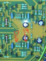
I wish the circuit board as labelled with the part nos. Looking at pictures of my Stageline, I think R14 is not 62K but is already 100K.
R17 is 100K as per the 323 Schematic. See pic. - I’ve labelled one channel
Can you go above 100K for R14 or is it not recommended?
Attachments
I guess you can go above 100 kohm. Is there any way you can measure how many decibels too little you get at 30 Hz or 20 Hz? That would help to estimate how far above 100 kohm you have to go.
Hi Marcel. Well I have a test record with a 20Hz-20KHz test tone sweep and also pink noise. If I could record this into a computer and analyse with REW (maybe using the real time analyser) it might be useful.
I could then compare to a few of the other phono stages I’ve got that have sufficient bass.
How far in the value would be sensible to go to with R14? I guess another strategy is just to buy some different resistor values and try them.
Do you have to change R17 as well or can I leave it as it is?
I could then compare to a few of the other phono stages I’ve got that have sufficient bass.
How far in the value would be sensible to go to with R14? I guess another strategy is just to buy some different resistor values and try them.
Do you have to change R17 as well or can I leave it as it is?
Attachments
- Home
- Source & Line
- Analogue Source
- NAIM Stageline phono stage Bass issue