Hi, I was building new enclosure for my Kef Q150 drivers, I tried to take the crossover out by too much force and snapped one in half....... What are my options here? Not sure how I go about making a new one or repairing it. Cannot see anywhere where I can just buy a replacement?
Any help much appreciated, thanks
Any help much appreciated, thanks
Attachments

Typical way to make a crossover from scratch is to make a small component mounting board of something like 1/8 inch thick hardboard, ABS, or whatever you like to work with. Drill holes in it for component mounting, and wire point to point with soldered in wire or component legs. Since the legs are too short to do much with on yours, you'd need to add wires.
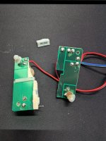
If you want to salvage the board you have, you'll need to get it glued/screwed/whatevered back into one piece, scrape off the solder mask (the green over the copper) in required spots, then bridge the gaps with wire that you solder to each side of the break.
And you'll need to replace that resistor, obviously.
If you contact KEF directly, they might sell you a crossover board. Some manufacturers want proof of ownership on parts, so if you didn't buy them from an authorized retailer that might be an issue. It's still worth contacting them though if neither of the above options work for you.
Since it looks like a single-layer board, you just need to replicate what the visible solid areas of copper are doing with wires. I would lay out the new and old boards the same way to make things easier to track.
If you trace everything down starting from the input, it's likely that you'll just have an inductor in-line with the woofer, and a capacitor and resistor in series with the tweeter.
This image shows all the labels more clearly.
www.diyaudio.com/community/threads/kef-q150-breeding.402547/

If you trace everything down starting from the input, it's likely that you'll just have an inductor in-line with the woofer, and a capacitor and resistor in series with the tweeter.
This image shows all the labels more clearly.
www.diyaudio.com/community/threads/kef-q150-breeding.402547/
If you trace everything down starting from the input, it's likely that you'll just have an inductor in-line with the woofer, and a capacitor and resistor in series with the tweeter.
That is correct.
This is the crossover schematic for the Q100 - same layout as for the Q150 - just different component values:
cheers I think I will have a go at rewiring
+ IN
│
├──(INDUCTOR 0.8mH)── LF+ (Woofer)
│
├──(CAPACITOR 3.7µF)──(RESISTOR 1.35Ω)── HF+ (Tweeter)
│
- IN
├────────────── LF- (Woofer)
├────────────── HF- (Tweeter)
Is this correct?
+ IN
│
├──(INDUCTOR 0.8mH)── LF+ (Woofer)
│
├──(CAPACITOR 3.7µF)──(RESISTOR 1.35Ω)── HF+ (Tweeter)
│
- IN
├────────────── LF- (Woofer)
├────────────── HF- (Tweeter)
Is this correct?
Sorry, I didn't see your post #6 when I submitted my post #7.
Woofer Section: From input +ve go to inductor. From inductor go to woofer +ve. From woofer -ve go to input -ve.
Tweeter Section: From input +ve go to capacitor. From capacitor go to resistor. From resistor go to tweeter -ve. From tweeter +ve go to input -ve.
P.S. The resistor is 1.3 ohm, not 1.35.
Woofer Section: From input +ve go to inductor. From inductor go to woofer +ve. From woofer -ve go to input -ve.
Tweeter Section: From input +ve go to capacitor. From capacitor go to resistor. From resistor go to tweeter -ve. From tweeter +ve go to input -ve.
P.S. The resistor is 1.3 ohm, not 1.35.
Last edited:
OK - I was going by the photo in post #4.
1.3 ohm resistors are available here: https://willys-hifi.com/collections...tzen-superes-10w-1-3-ohm-1-crossover-resistor
There should be no audible difference between 1.3 and 1.35 ohm. If there were to be you could always wire a 1.3 ohm in the unbroken crossover.
1.3 ohm resistors are available here: https://willys-hifi.com/collections...tzen-superes-10w-1-3-ohm-1-crossover-resistor
There should be no audible difference between 1.3 and 1.35 ohm. If there were to be you could always wire a 1.3 ohm in the unbroken crossover.
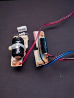
Use acetone to clean the broken edges, stick with Super Glue, jumper wire the broken tracks.
Keep it level, and do it in a ventilated area.
If needed, put new parts to replace broken or damaged parts....I just glanced over the posts.
Fiber glass tape, used in motor winding, can be used with two part epoxy adhesive to repair phenolic materials, use if needed, observe the usual precautions about cleanliness and ventilation while doing so.
Super Glue is just a brand, many companies make that class of product, no ties to anybody.
Not sure what I've done wrong, but

Purple is repaired
Here are my two modded (small profile) q150s vs my other two q150s

Purple is repaired
Here are my two modded (small profile) q150s vs my other two q150s
Not sure what I've done wrong, but
What, exactly, did you do? How did you make the repair? Did you reverse the tweeter's electrical polarity?
It would be hard to make a mistake assembling such a simple crossover circuit.
jumper wire the broken tracks, followed this
Woofer Section: From input +ve go to inductor. From inductor go to woofer +ve. From woofer -ve go to input -ve.
Tweeter Section: From input +ve go to capacitor. From capacitor go to resistor. From resistor go to tweeter -ve. From tweeter +ve go to input -ve.
Not sure what I've done wrong, tho I did replace the resistor with 5w 1.5ohm as that is all I had
Ugh bummer sorry that happened to your Kef crossover. So correct me if am wrong? But using a 1.5 ohm resistor and not a 1.35 ohm resistor can change things in a crossover. So I would have called the Kef speaker company and explained what happened and asked how you could buy the right resistor for your crossover. If you’re in England it should be cheap for shipping. Or you could buy it from Willys and wait a few days. I bought from willy’s in the past and I got my product in a week and I live in Michigan. Jeff
I bet Farnell UK has the resistor. If you can't get a 1.3 ohm 5 w parallel two 0.67 ohm 3 watt resistors. I tried to look it up but their new selector table is locking up my ancient computer. They do have a handling charge for 1 L orders, so buy a pound of solder heat sink compound or a tool on the order.
That change alone would not create a deviation of this magnitude or shape. Can you post an image of your repair?1.5ohm as that is all I had
- Home
- Loudspeakers
- Multi-Way
- Damaged KEF Q150 - What are my options?