Gentlepersons,
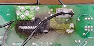
I recently acquired a 20-ish year old Energy EPS-100 dual-driver subwoofer with a 100W MOSFET plate amplifier. I opened it up to clean the scratchy potentiometers, and found a rather distressing, clearly long-standing situation in the neighbourhood of the power supply:


It has to be noted that the unit is still in working condition, and packs quite a punch at that.
Sadly I have no schematics, so I'm left trying to puzzle out what's going on here, and why. I'd be grateful if someone has a better theory than the one I've come up with (below). Near as I can tell, the power supply in the vicinity of the input, where the PCB is baked, looks something like this:

My theory is this:
So again, my questions to the wise ones here, are:
The Plumber
I recently acquired a 20-ish year old Energy EPS-100 dual-driver subwoofer with a 100W MOSFET plate amplifier. I opened it up to clean the scratchy potentiometers, and found a rather distressing, clearly long-standing situation in the neighbourhood of the power supply:
It has to be noted that the unit is still in working condition, and packs quite a punch at that.
Sadly I have no schematics, so I'm left trying to puzzle out what's going on here, and why. I'd be grateful if someone has a better theory than the one I've come up with (below). Near as I can tell, the power supply in the vicinity of the input, where the PCB is baked, looks something like this:
- V1 is line AC
- Thermal switch an fuse are just there for illustration
- R1 is the (measured) ~500 ohm resistor baking the PCB
- Q1 seems to be a 2N6071 triac.
- An R2 of two ohms stands in for the power transformer and the rest of the amplifier at full draw. No, I haven't run a simulation.
- The triac's trigger comes from an MOC3023 optoisolator device (ISO1 in the picture, and not shown in the simplification above).
My theory is this:
- With no audio signal at the inputs, R1 drops input AC voltage so that the transformer powers the amplifier at a lower voltage
- This lower power supply voltage is enough to run signal autodetection at the line level audio inputs, but not enough to power the main amplifier.
- When signal is detected, it triggers the isolator to turn on the triac, effectively bypassing R1 and putting all the line voltage across the transformer's input.
So again, my questions to the wise ones here, are:
- Am I crazy?
- Does anyone have a service manual or at least a schematic for this old unit?
And my most pressing question: - Given that I don't particularly care about the unit's ability to automatically power up based on input signal, wouldn't it be safer to replace { R1, C1, Q1 } with a proper AC power switch?
The Plumber
Last edited:
1. Not crazy! You caught it just in time!
How much power do you suppose is being dissipated by R1? Even just 1W for a long time would cause charring like this...
3. I think you should just space R1 off the board another inch. Don't fix what ain't broke (yet?)...
How much power do you suppose is being dissipated by R1? Even just 1W for a long time would cause charring like this...
3. I think you should just space R1 off the board another inch. Don't fix what ain't broke (yet?)...
Hey there! Thanks for your reply.
When the unit is in idle (no input signal; auto-on not triggered) there's 43V across R1 (~3.7W). That leaves ~80V across the power transformer, and so between 5 and 6 W consumed by the auto-detect circuitry (in "off" state).
5 or 6W at idle seems surprisingly high, which, if unexpected by the designer, may explain why R1 is cooking the way it is.
80V across the power transformer at idle also means that the input circuitry is running at ~2/3 of its nominal "on" voltage, which doesn't seem like a big savings in power.
Boy, I wish I had a schematic. I'm going to take a look at power rails in idle and on states and try to get some idea of how much it should be consuming in idle.
You're quite right about it not being broke yet... but 4W from that resistor gives me considerable pause.