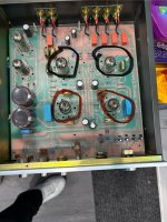
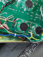
Hi all I have just put on the 728a preamp but sadly it went with a little bang but now only the bottom 2 valves get hot but the top 2 are staying cold. Both small rectifier are working as they should do. Could someone point me into the right direction on the picture where it’s circulated red they are working as they should do. But the black circled ones are stone cold.where should I look first. Many thanks in advance
Attachments
Ok dont panic
There must be a regulator for the heaters somewhere in the other side left at the psu . I think that this is the potential problem. The top tubes staying cold because there is no voltage at their heaters. The regulator is after the rectifier. I had the exact same issue with my pre and it was the 7812 regulator.
Find the regulator (if any) and with a multimeter check the output voltage.
The regulator has 3 pins. From the front side The middle is the common ground the left is the input and the right is the output.

Ok
After a research i saw that there are multiple versions of this pre and from the pics i see that yours in top left corner behind the left top tube is missing the regulator that i wrote you in my previous post. The other Xiang Sheng 278a i saw has indeed this regulator in this spot.
Someone with more knowledge than mine could help more because there is a chance that i am completely wrong about this
Thank you there seems to be several 728a I don’t know which one I have. Could someone edit my photo and mark where I should start to investigate many thanks
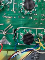
Thank you monstercore what I will do is take the board out and check the underside of the pcb board and see if I see any sort of damage there. I think the model I have is one of the latest version as it does not have the big green army caps on the board. Looks like they have been replaced with wima caps instead also I was thinking it could possibly be the 1uf caps blown next to the valve/tube sockets once again thank you
I think your heaters will be 12v dc for heaters in series or 6.3v dc for heaters in parallel. So you likely have a 7812 reg for 12v that is the most commonThank you there seems to be several 728a I don’t know which one I have. Could someone edit my photo and mark where I should start to investigate many thanks
According to the schematic the heaters are being fed with 12.6 Vac. The heater supply is 'lifted' to ca. 54 Vdc by the voltage divider made of 5R1 and 5R2/5C4.
Note that the two leads of the 12.6 Vac winding of the power transformer are tagged "AC4". The circuit board in picture in post #1 shows "AC4" between the two tubes that are encircled in red. This also points to the heaters being fed with 12.6 Vac.
What puzzles me is that post #1 seems to mean that the heaters of the two tubes that are encircled in black (which I think are the 12AT7's) do not work. But I do not see any damage to the two tracks/connectors going from "AC4" to the tubes encircled in black.
I think that removing the 12AT7's and 12AU7's and then measuring if the 12.6 Vac appears on pins 4 and 5 of the tubes encircled in black would be the best first step.
If the 12.6 Vac does appear between pins 4 and 5 of the tubes encircled in black, then measure the dc voltage between ground and pin 4 or pin 5 (it does not matter which of the two pins you choose). This is to check if the voltage divider made of 5R1 and 5R2/5C4 is still OK.
It seems very unlikely to me that the heaters of both 12AT7's went open at the same time. But just to be sure, measure the resistance between pins 4 and 5 of each 12AT7 to check if there is continuity.
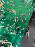
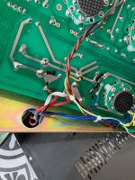
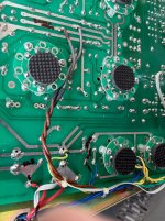
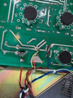
Hi all thank you for the replies back I have disconnected all the wires. And I now have full access to the components. Where should I start measuring from. There is no clear indication where it may have blown. The Board is looking okay or less I have missed something.
Many thanks
Many thanks
Attachments
- Home
- Amplifiers
- Tubes / Valves
- Xiang Sheng 278a