Hi,
a well-known one has bought such an Amp https://de.aliexpress.com/item/1005006773111211.html?gatewayAdapt=glo2deu
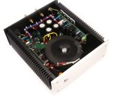
The Amp gives hum to the speakers. He measured about 34 dB. He ask me for a look to this amp. I have a little bit more knowledge...little
There was a connection between PE at different places in his amp. One spacer had connection to one heatsink on the boards, used for the drivers, wich is grounded.
Input minus was grounded on both boards and to PE, because PE is connected to the housing. The chinese used the board metal spacers for grounding.
No loopbreaker or resistor in the amp between PE and powerground. Something like a starpoint was made on the power pcb. Powerground and speakers are connected.
I know that the L20.5 has no groundlift resistor. PE ist connected to the housing now, no connection to the powerground anymore, but the amp is still humming.
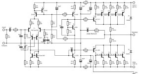
I remembered i found a schematic in the i-net. I have made a picture from this schematic, hoping it is correct.
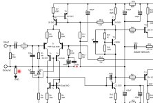
My idea is to put a ground lift resistor in at the input, its missing. I have drawn a new plan with my little knowledge. Could you please tell me if i am right with my drawing ?
I want to use a starpoint, make a connection to the signal ground and will use a loopbreaker. I had great sucsess (with help in this forum) using this things in my FH9 Amp to lower the offset. ( i got no hum before).
Picture 3 shows the schematic. I have marked the changes in red i want to make on picture 4.
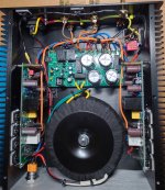
I have seen that the rca wires are very long, behind the L20.5 board and near to the transformer. I will try to turn the case heatsinks to get a shorter way.
Thanks for helping
Peter
a well-known one has bought such an Amp https://de.aliexpress.com/item/1005006773111211.html?gatewayAdapt=glo2deu
The Amp gives hum to the speakers. He measured about 34 dB. He ask me for a look to this amp. I have a little bit more knowledge...little
There was a connection between PE at different places in his amp. One spacer had connection to one heatsink on the boards, used for the drivers, wich is grounded.
Input minus was grounded on both boards and to PE, because PE is connected to the housing. The chinese used the board metal spacers for grounding.
No loopbreaker or resistor in the amp between PE and powerground. Something like a starpoint was made on the power pcb. Powerground and speakers are connected.
I know that the L20.5 has no groundlift resistor. PE ist connected to the housing now, no connection to the powerground anymore, but the amp is still humming.
I remembered i found a schematic in the i-net. I have made a picture from this schematic, hoping it is correct.
My idea is to put a ground lift resistor in at the input, its missing. I have drawn a new plan with my little knowledge. Could you please tell me if i am right with my drawing ?
I want to use a starpoint, make a connection to the signal ground and will use a loopbreaker. I had great sucsess (with help in this forum) using this things in my FH9 Amp to lower the offset. ( i got no hum before).
Picture 3 shows the schematic. I have marked the changes in red i want to make on picture 4.
I have seen that the rca wires are very long, behind the L20.5 board and near to the transformer. I will try to turn the case heatsinks to get a shorter way.
Thanks for helping
Peter
Attachments
Last edited:

Ok,
Thanks.
I can use 1n951 x2 and one 100 nf wima. I think i make a little breadboard then.
Peter
Thanks.
I can use 1n951 x2 and one 100 nf wima. I think i make a little breadboard then.
Peter
Hi...
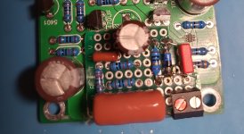
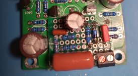
I had to make a new input with a little breadboard. Nothing to cut, i found something like a groundgplane. The 100 nf parallels to the 470µf feedback capacitor does not exist. Perhaps i solder one in. I could make two connections with a silver wire. Feedback to the resistor r10, 330 ohm and 10 ohm groundlift to powerground. If i make measurements all seems to be ok on its right place. Put 2 diodes antiparalled in and a parallels capacitor 100nf to the RG. Another connection went to the input transistor.
I think i can turn the heatsinks from one side to the other. In the original amp one rca wire has a lenght for about 40 cm. Both inputs were near to the transformer...
Not much right in that amp.....
Greets
Peter
Attachments
Last edited:
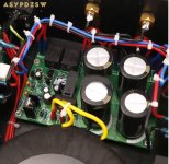
Now, i could not hear any hum anymore in my speakers with the LJM L20.5.
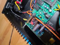
I have turned the heatsinks to keep the input away from the transformer, had to wire all new. Set fast on connectors for ground/+-. Connected the new groundliftresistor with a little wire to input -. Set a loopbreaker with connection to PE and ground.
The groundliftresistor has two 1n914 diodes anti parallel and a 100 nf capacitor parallel.
The little breadboard has 3 connections. One to the gound for the new groundlift, one to the input transistor, and at last the feedback capacitor. Its possible to change back all changes, the L 20.5 board is unchanged.
What the chinese people had done...mostly nonsense, can not understand...
Greets
Peter
Attachments

- Home
- Amplifiers
- Solid State
- L20.5, finished Amp with Hum